X線回折(超高速物質科学)
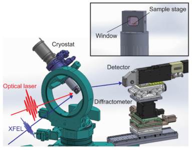
XFELを使った物質科学研究では、X線回折法と同期レーザーを組み合わせた、ポンプ・プローブ(時間分解)X線回折実験が多く実施されています。本ページでは、SACLAにおける時間分解X線回折実験について紹介します。
基本性能・成果
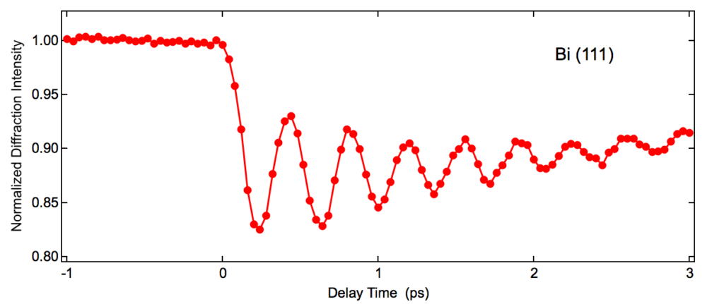
Biのコヒーレントフォノン測定例
波長800 nmの超短パルスレーザーを励起光として、Bi薄膜の(111)回折強度の時間変化を測定

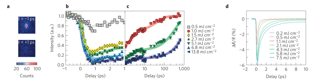
モット絶縁体Sr2IrO4の磁性変化の観測
波長2 μmの超短パルスレーザーを励起光として、Sr2IrO4の磁気回折強度の時間変化を測定
M. P. M. Dean et al., Nature Materials 15, 601 (2016).
Destruction and recovery of charge and 3D magnetic order in Sr24
実験装置
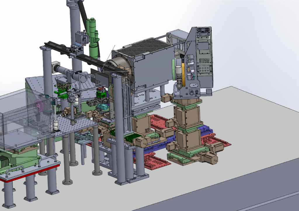
Huber回折計
SACLAでは共用多軸回折計としてHuber社の4-Circle Diffractometer 5042を使用しています。試料を取り付けるゴニオメータは同じくHuber社のGoniometer Head1003-MSを標準としています。
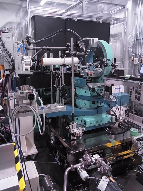
共用多軸回折計を用いた実験の様子(仮)
回折計全体図ダウンロード
サンプルホルダー(ゴニオピン)(資料添付予定)
その他の回折計
Huber社の回折計以外にも、KOHZU社のステージを組み合わせたセットアップなども構築可能です。例として、以下に示すようなdiffuse scatteringの実験実績があります。詳細はXFEL利用研究推進室(このメールアドレスはスパムボットから保護されています。閲覧するにはJavaScriptを有効にする必要があります。)までお問い合わせください。

diffuse scattering実験のセットアップ例(仮)
検出器
X線回折実験では、主にMPCCDを検出器として使用しています。アライメントのためにPhotodetector(PD)や2次元高分解能検出器を使用することも可能です。
冷却関連
試料を冷却し、室温以下の温度で測定するために、下記の冷却装置が使用可能です。
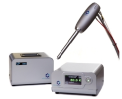
液体窒素吹き付け装置
液体窒素を用いた吹き付け型冷却装置として、Oxford Cryosystems社製Cryostream 800 Plusが使用できます。制御可能な温度範囲は約100~400 Kです。
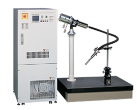
気体窒素吹き付け装置
大気中の窒素ガスを用いた吹き付け型冷却装置として、Rigaku社の吹き付け装置が使用できます。制御可能な温度範囲は約100 K~室温です。
GM冷凍機
GM冷凍機を上述のHuber回折計に搭載し、広い入射及び出射角度を保ちながら試料の冷却が可能です。制御可能な温度範囲は約10 K〜室温です。
Y. Kubota et al., Applied Physics Letters 122, 092201 (2023).
ソフトウェア
回折計の制御ソフトとして、Certified Scientific Softwareのspecが使用可能です。
運転パラメータ(EH2@BL3)
時間分解X線回折実験は主にBL3のEH2で実験を行っています。
XFELパラメータ
| 光子エネルギー(基本波) | 4-20 keV |
| パルスエネルギー | 光子エネルギーに依存(下図参照) |
| エネルギー幅(ΔE/E) | ~0.5%(ニ結晶分光器なし) |
| 繰り返しレート | 30 Hz(BL2&3同時運転時) |
参考文献:
M. Yabashi et al., J. Synchrotron Rad. 22, 477 (2015).
K. Tono et al., J. Synchrotron Rad. 26, 595 (2019).
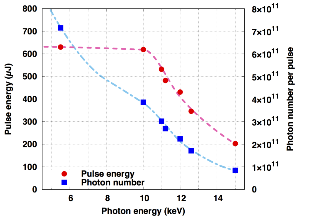
(参考)光子エネルギーとパルスエネルギー・光子数の関係(BL3の場合)

X線集光特性
Optical parameters (CRLs)
| Material | Beryllium |
| Shape of lenses | Paraboloid |
| Radii of curvatures (R) | 200, 500 µm |
| Maximum number of lenses | 31 with R = 200 µm |
| 15 with R = 500 µm | |
| Focal length | 2.5 m |
| Spatial acceptance | > 0.9 mm |
| Divergent angle | > 0.1 mrad* |
| Typical focal size @10 keV | 1-2 µm FWHM* |
*使用するレンズの数や波長に依存します。
参考文献:
T. Katayama et al., J. Synchrotron Rad. 26, 333 (2019).
光学レーザー特性
| 基本波 | 2倍波 | 3倍波 | 4倍波 | |
| Wavelength | 800 nm | 400 nm | 267 nm | 200 nm |
| Pulse Energy (Max.) | ~12 mJ | ~0.5 mJ | ~0.2 mJ | ~0.02 mJ |
| Pulse Duration | ~40 fs | ~30 fs | ~50 fs | |
| Rep. Rate | 60 Hz | 60 Hz | 60 Hz | 60 Hz |
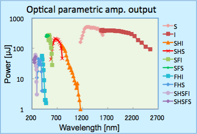
上記に加え、光パラメトリック増幅器(OPA: Optical Parametric Amplifier)からの光を利用可能です。使用可能な波長域は0.25-2.6 µmで、下図のようにパルスエネルギーは波長に依存します。
(参考)
低光子エネルギーのXFELを使用する実験、小さなビームサイズが必要な実験などに対しては、KBミラーが常設されたEH4cも使用可能です。詳細は以下のページをご参照ください。
X線集光特性
測定までの調整作業
ビームタイム前までにスタッフ行うこと
以下の作業はビームタイム前にSACLAのスタッフが行います。
- ・装置を実験ハッチに搬入
- ・XFELのスペクトル、光軸、集光の調整
- ・同期レーザースペクトル、光軸、集光の調整
- ・XFELと同期レーザーのラフな空間合わせ
- ・高速PDを使ったXFELと同期レーザーのタイミング調整(精度は±10 ps程度)
- ・タイミングモニターの調整
ビームタイム開始後にユーザー自身が行うアライメント
時間分解X線回折実験を行うために、ユーザー自身に行っていただく、最低限のアライメントを以下に示します。
- ・回折計の回転中心出し
- ・回転中心をXFEL照射位置にアライメント
- ・XFELと同期レーザーの空間合わせ(例:Ce:YAG)
- ・XFELと同期レーザーのタイミング合わせ(例:Bi、Ce:YAG)
測定手順
アライメント後に行う、実際の測定手順例を以下に示します。
1.試料をゴニオメーターに設置
2.ゴニオメーターのモーター軸を使って回転中心に試料を移動
3.試料下流に設置したPDを使って半割り
4.目的の回折ピークへ回転軸の角度を調整し、MPCCDでピークを探索
5.同期レーザーを入射し、タイミング0の前後で変化を確認
6.ディレイステージをスキャンすることで、時間分解測定を実施
7.最終的にはRunControlでスキャンを実施し、MPCCDとタイミングモニター(OPAL)の画像データを保存
8.タイミングモニターを用いて、ショット毎のジッターを補正
マニュアル他
SACLA測定手順マニュアル ダウンロード
(RunControlの使い方等含めたものに更新予定)
データ解析マニュアル ダウンロード
さらに詳しい解析手法を知りたい方はSACLA HPC Portal site (VPN接続が必要です)をご参照ください。
X-Ray Diffraction (Ultrafast Material Science)
For research in material science using XFEL, many pump-probe (time-resolved) X-ray diffraction experiments that combine X-ray diffraction and synchronous lasers are performed. This page introduces the time-resolved X-ray diffraction experiments at SACLA.
Basic Performance and Results
Examples of coherent phonon measurements of Bi
Using an ultrashort pulse laser with a wavelength of 800nm as excitation light, the Bi thin film (111) time change of the diffraction intensity is measured.
The magnetic changes in the Mott insulator Sr2IrO4 observation.
The time change of the magnetic diffraction intensity of Sr2IrO4 using an ultrashort pulse laser with a wavelength of 2 μm as the excitation light can be measured.
M. P. M. Dean et al., Nature Materials 15, 601 (2016).

2IrO4
Experimental Equipment
Huber Diffractometer
SACLA uses the Huber 4-Circle Diffractometer 5042 shared multi-axis diffractometer. The goniometer, to which the sample is attached, is also standardized by the Huber Goniometer Head1003-MS.
Experiments using the shared multi-axis diffractometer (temporary
Sample holder (adjustment pin) (for attaching materials)
Other diffractometers
In addition to the Huber diffractometer, it is also possible to build a setup that combines KOHZU stages. For examples there are experiments with diffuse scattering shown below. For details, please contact the XFEL Utilization Division (このメールアドレスはスパムボットから保護されています。閲覧するにはJavaScriptを有効にする必要があります。).
Examples for setting up diffuse scattering equipment (temporary)
Detector
For X-ray diffraction experiments, the MPCCD is generally used as the detector. Photodetectors (PD) and scintillator-based 2-dimensional detectors are also available.
PD
2-Dimensional high-resolution detector
Refrigeration
The following refrigeration devices can be used to cool the sample and measure it at temperatures below room temperature.
Liquid nitrogen spraying equipment
The Cryostream 800 Plus, manufactured by Oxford Cryosystems, can be used as a liquid nitrogen spraying cooling device. The controllable temperature range is approximately 100~400 K.

Gas nitrogen spraying equipment
The Rigaku spraying equipment uses nitrogen gas for the cooling equipment. The controllable temperature range is from 100K to room temperature.

GM freezer
Currently under development
Software
The Certified Scientific Software spec is available as diffractometer control software.
Operating Parameters (EH2@BL3)
The time-resolved X-ray diffraction experiments are generally conducted with EH2 at BL3.
XFEL parameters
| Photon energy (fundamental wave) | 4-20 keV |
| Pulse energy | To photon energy (See figures below) |
| Energy width(ΔE/E) | ~0.5%(without a two crystal spectrometer) |
| Repetition rate | 30 Hz(BL2&3 simultaneous operation) |
References:
M. Yabashi et al., J. Synchrotron Rad. 22, 477 (2015).
K. Tono et al., J. Synchrotron Rad. 26, 595 (2019).
(Reference) The relationship between photon energy and pulse energy / photon number (For BL3)
 </p
</p
X-ray focusing characteristics
| Optical parameters (CRLs) | |
| Material | Beryllium |
| Shape of lenses | Paraboloid |
| Radii of curvatures (R) | 200, 500 µm |
| Maximum number of lenses | 31 with R = 200 µm 15 with R = 500 µm |
| Focal length | 2.5 m |
| Spatial acceptance | > 0.9 mm |
| Divergent angle | > 0.1 mrad* |
| Typical focal size @10 keV | 1-2 µm FWHM* |
*This depends on the wavelength and number of lenses used.
References:
T. Katayama et al., J. Synchrotron Rad. 26, 333 (2019).
Optical laser characteristics
| Fundamental wave | 2nd Order Harmonic | 3rd Order Harmonic | 4th Order Harmonic | |
| Wavelength | 800 nm | 400 nm | 267 nm | 200 nm |
| Pulse Energy (Max.) | ~12 mJ | ~0.5 mJ | ~0.2 mJ | ~0.02 mJ |
| Pulse Duration | ~40 fs | ~30 fs | ~50 fs | |
| Rep. Rate | 60 Hz | 60 Hz | 60 Hz | 60 Hz |
In addition to the above, light from the Optical Parametric Amplifier (OPA) is available. The available wavelength range is 0.25-2.6 µm, and the pulse energy depends on the wavelength as shown in the figure below.

(Reference)
For experiments using low photon energy XFEL and experiments that require small beam sizes, EH4c, which has a permanent KB mirror installed, can be used. For details, please refer to the following page.
Adjustments before the Measurement
What the staff do before the beam time:
The following tasks are performed by SACLA staff before the beam time.
- ・Bring the equipment to the experimental hutch
- ・Adjust and focus the XFEL spectrum and optical axis
- ・Adjust and focus the synchronous laser spectrum and optical axis
- ・Roughly align the space between the XFEL and synchronous laser
- ・Adjust the timing of the XFEL and synchronous laser using the high-speed PD (accuracy is approximately ±10 ps)
- ・Adjust the timing monitor
The alignment is performed by the user after the start of the beam time.
The minimum alignments that the user must perform in order to obtain time-resolved X-ray diffraction experiments are shown below.
- ・Centre the rotation of the diffractometer
- ・Align the center of rotation with the XFEL irradiation position
- ・Align the space between the XFEL and the synchronous laser (Example: Ce:YAG)
- ・Align the XFEL and synchronous laser (Example: Bi, Ce:YAG)
Measurement Procedures
Examples of actual measurement procedures after the alignment is shown below.
1.Install the sample on the goniometer
2.Move the sample to the center of rotation using the motor shaft of the goniometer
3.Half split by using the PD installed downstream of the sample
4.Adjust the angle of the axis of rotation to the intended diffraction peak, then search the peak with the MPPCD
5.Once the synchronous laser is incident on the system, confirm the changes before and after timing 0
6.Perform time-resolved measurements by scanning the delay stage
7.Finally, scan with RunConrol and save the image data for the MPCCD and the timing monitor (OPAL)
8.Use the timing monitor to correct the jitter for each shot
Manuals and more
SACLA measurement procedure manual download
(Scheduled to be updated to include how to use RunControl)
Data analysis manual download a>