CDI(単粒子構造解析)
コヒーレント回折イメージング(coherent diffraction imaging; CDI)は、ナノメートルからマイクロメートルサイズの微小な試料を対象としたイメージング手法です。試料のサイズや必要な分解能に応じて、1 μmまたは100 nm集光ビームを利用して測定を行います。
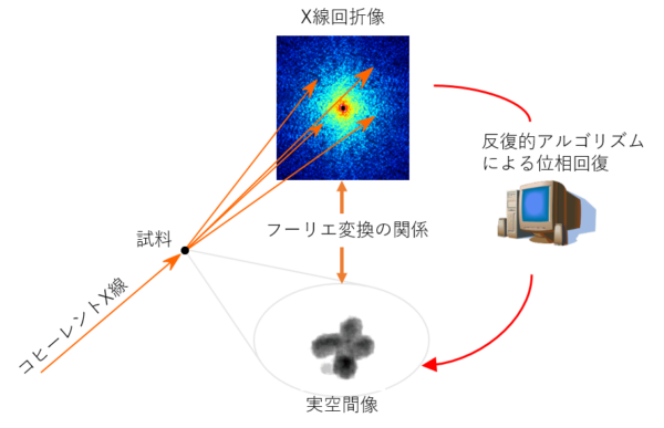
CDI実験の概念図
参考文献:
Y. Nishino et al., Phys. Rev. Lett. 102, 018101 (2009).
基本性能・成果
共用装置
ここでは、CDI実験の共用装置である MAXIC(Multiple Application X-ray Imaging Chamber) を利用した成果を紹介します。現在では以下の2種類の後継機が共用装置として稼働しています。
MAXIC-II
主にサブミクロンスケールの試料を対象にした装置で、MAXICの基本性能を引き継ぐものです。試料を 1 μm集光ビームで照明し、10 nmオーダーの分解能(q < 0.1 nm-1 @4 keV)でX線回折像を記録します。ナノ秒光学レーザーを利用したポンププローブ計測も可能です。
MAXIC-S
装置に内蔵された集光ミラー光学系により、試料を 100 μmビームで照明することが可能です。最小で約2 nmの分解能(q < 0.5 nm-1 @4 keV)でX線回折像を記録します。
参考文献:
C. Song et al., J. Appl. Cryst. 47, 188 (2014).
測定例:生きた細胞のイメージング
北海道大学の西野教授の研究グループは、マイクロ液体封入アレイ(micro-liquid enclosure array; MLEA)の中の Microbacterium lacticum 細胞を対象としたCDI実験を行いました。 MAXICを利用した測定により、生きた細胞の内部を可視化することに成功しました。
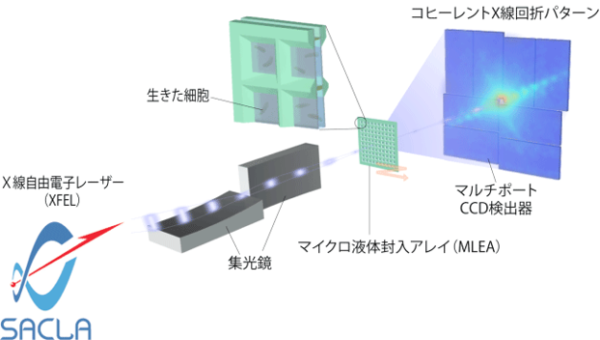
生きているMicrobacterium lacticum細胞のCDI実験
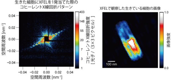
CDI実験で得られたコヒーレント回折像(左)とデータ解析により再構成された実空間像(右)
[2014年1月7日プレスリリースより]
参考文献:
実験装置
MAXIC-II
MAXICの主な機能を引き継ぐとともに、光学レーザーを利用したポンププローブ計測のための機能が追加された装置です。本装置の基本構成要素として、真空チャンバー内に2組の4象限スリットと試料マニピュレーターが 設置されています。必要に応じて、チャンバー内の光学ブレッドボード上にポンプレーザー用の光学素子をレイアウトすることも可能です。
基本的に、チャンバーはビームラインの汎用集光システムに接続され、マイクロX線ビームを利用して測定が行われます。ビームラインの光学系からの 寄生散乱X線 は、チャンバー内の2組の4象限スリット によって除去されます。試料からの回折X線の検出には、MPCCD検出器を利用します。
試料は、 多くの場合 窒化ケイ素薄膜などに担持され、 試料マニピュレーター に搭載されます。XFELパルスを照射された試料は破壊されてしまうため、照射するごとに新たな試料を照射位置まで移動させます。チャンバー には試料を観察するための顕微鏡が備えられており、照射位置の調整などに利用されます。
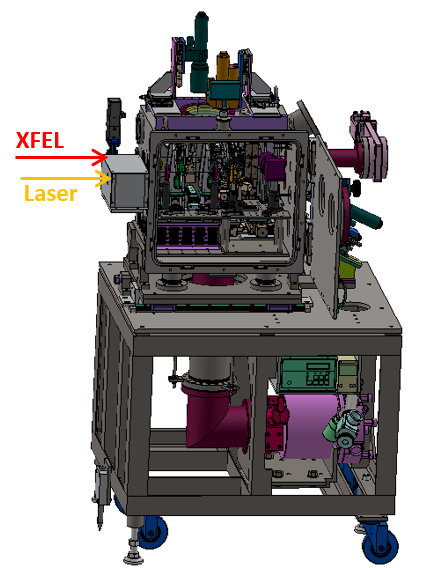
MAXIC-II: 装置全体
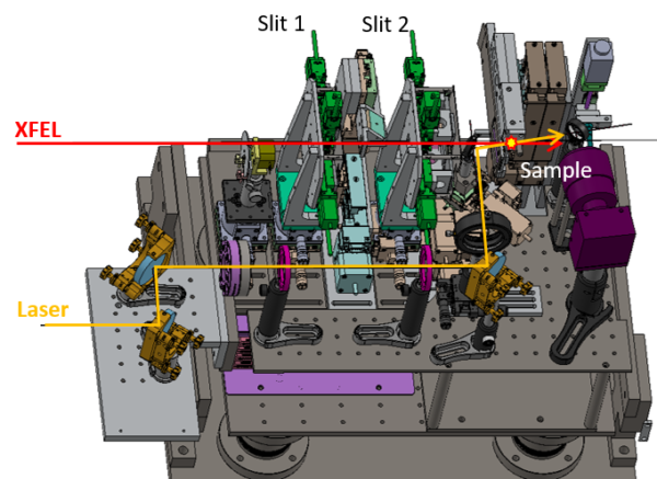
MAXIC-II: 真空チャンバー内部
MAXIC-S
この装置は専用の多層膜集光ミラーを内蔵し、スポットサイズ100 nm程度のXFELビームを試料に照射することができます。高強度の集光ビームを利用することで、試料の高分解能イメージを取得することが可能です。集光ミラーの他には、2組の4象限スリット、試料マニピュレータ、試料観察用顕微鏡、試料交換用ロードロック装置などが備えられています。
※MAXIC-Sは、北海道大学の西野吉則教授のグループとの共同開発により整備されました。 また、SACLA基盤開発プログラムの課題として高度化が行われてきました。
参考文献:
T. Koyama et al., Microsc. Microanal. 24, 294 (2018).
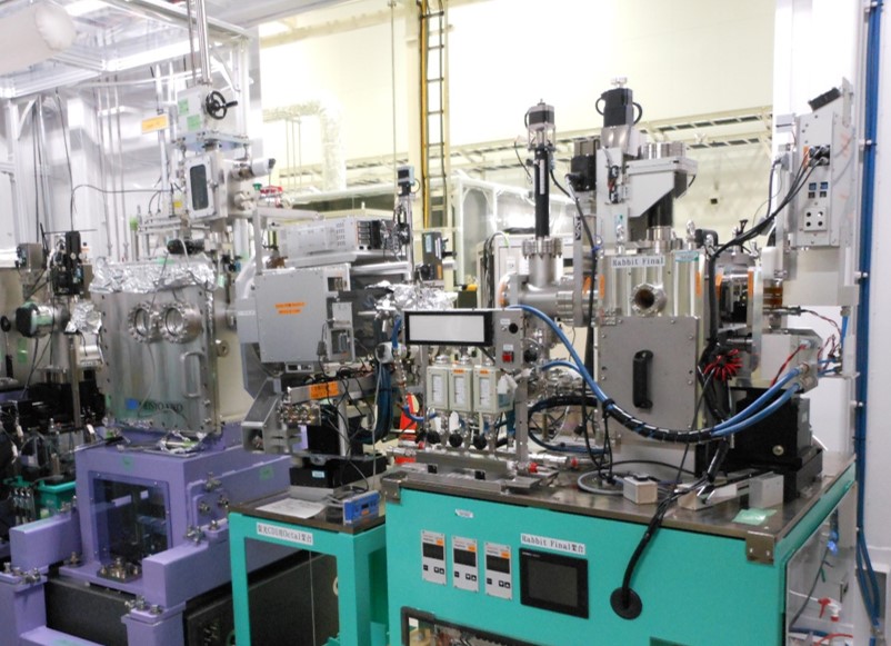
MAXIC-Sを利用したCDI実験システムの写真: 左が上流側で、MAXIC-S、Octal MPCCD検出器、Dual MPCCD検出器の順に配置されている。
検出器
コヒーレント回折像を記録するためにMPCCD検出器を使用します。広角領域をカバーするOctal MPCCD検出器と小角領域向けのDual MPCCDをタンデムに配置し、広い角度範囲で回折像を記録します。
運転パラメータ(EH3&4b@BL2)
CDI実験は、主にBL2のEH3&4bで行われています。
XFELパラメータ
| 光子エネルギー(基本波) | 4-20 keV |
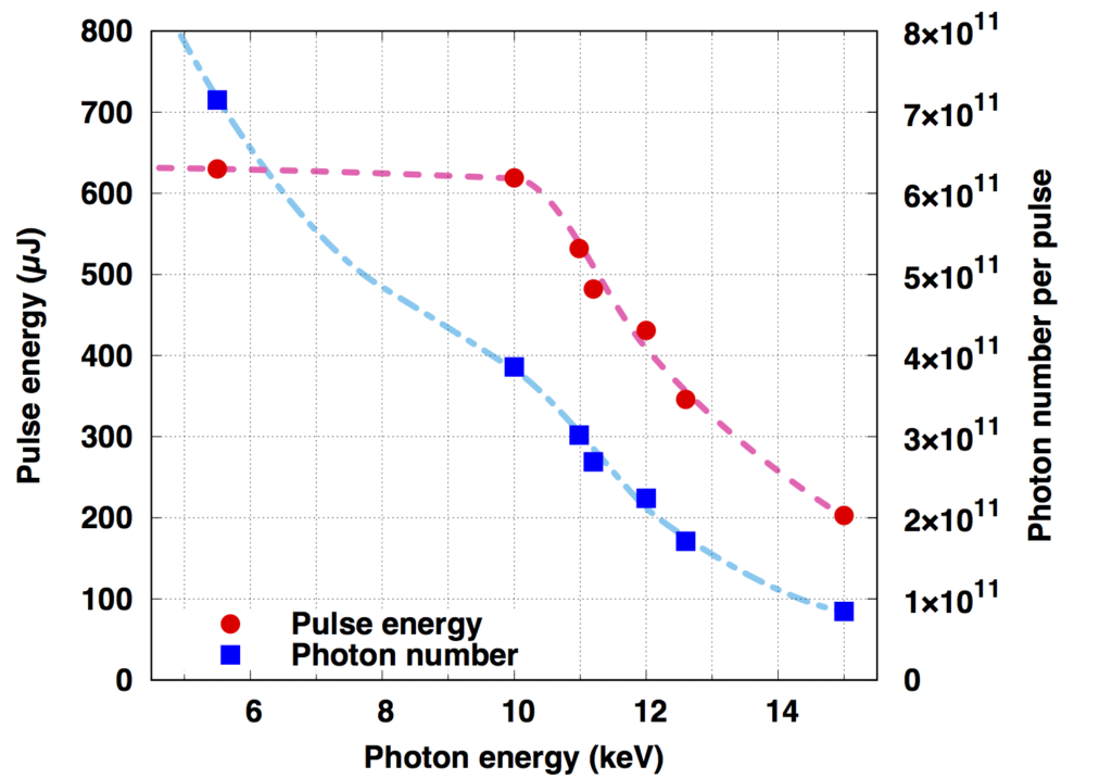
| パルスエネルギー | 光子エネルギーに依存(下図参照) |
| エネルギー幅(ΔE/E) | ~0.5%(ニ結晶分光器なし) |
| 繰り返しレート | 30 Hz(BL2&3同時運転時) |
参考文献:
M. Yabashi et al., J. Synchrotron Rad. 22, 477 (2015).
K. Tono et al., J. Synchrotron Rad. 26, 595 (2019).
(参考)光子エネルギーとパルスエネルギー・光子数の関係(BL3の場合)

光学レーザー特性
| グリーンレーザー Minilite, Continuum |
光パラメトリック発振器* NT232, Ekspla |
|
| Wavelength | 532 nm | 532 nm |
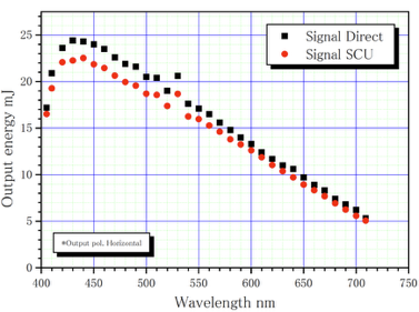
| Max. Pulse Energy | ~20 µJ | 波長に依存(下図参照) |
| Pulse Duration | 3-5 ns | 2-5 ns |
| Rep. Rate | 10 Hz | 30 Hz |
*光パラメトリック発振器(OPO: Optical Parametric Oscillator)のパルスエネルギーは波長に依存します。

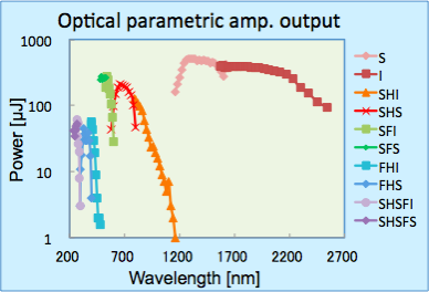
光パラメトリック増幅器(OPA: Optical Parametric Amplifier)からの光を利用可能です。使用可能な波長域は0.25-2.6 µmで、下図のようにパルスエネルギーは波長に依存します。
計測器配置
MPCCD検出器の標準的な配置
| MPCCD Octal | MPCCD Dual | |
| センサーエリア | 110 mm x 110 mm | 52 mm x 52 mm |
| MAXIC-II 標準的なカメラ長 |
1.5 m | 3 m(EH3に設置) 9 m(EH4bに設置) |
| MAXIC-S カメラ長 (固定) |
0.32 m | 1.6 m |
測定までの調整作業
ビームタイム前までにSACLAのスタッフが行うこと
以下の作業はビームタイム前にSACLAのスタッフが行います。
- ・装置を実験ハッチに搬入
- ・XFELのスペクトル測定、光軸調整
- ・XFEL集光光学系の調整
- ・4象限スリットのアライメント(租調整)
同期レーザーを使用するポンププローブ型実験の場合は、以下の作業も SACLAのスタッフが行います。
- ・同期レーザースペクトル、光軸、集光の調整
- ・XFELと同期レーザーのラフな位置合わせ
- ・高速PDを使ったXFELと同期レーザーのタイミング調整
ビームタイム開始後にユーザー自身が行う主な操作
CDI実験を行うために、ユーザー自身に行っていただく実験操作を以下に示します。
- ・試料交換とそれに伴う真空チャンバーの開閉や排気操作
- ・4象限スリットのアライメント(精密調整)
- ・試料位置の調整
- ・XFELと同期レーザー照射位置の精密調整(ポンププローブ型実験の場合)
測定手順
測定の流れ(MAXIC-IIの場合)
- 1.マニピュレーターに試料をマウントする。
- 2.MAXIC-IIチャンバーの真空排気を行う。
- 3.チャンバーに備え付けの長作動顕微鏡を利用して、試料をX線照射位置に対してアライメントする。
- 4.試料のスキャンのためのパラメーター(照射位置の座標など)を設定する。
- 5.MAXIC-IIチャンバーと検出器との間のゲートバルブを開放する。
- 6.RunControl GUIを用いて試料のスキャンと回折像の記録を開始する。
- 7.チャンバーを大気開放して試料を取り出す。
CDI(Single Particle Structure Analysis)
Coherent Diffraction Imaging (CDI) is an imaging technique for small samples of nanometer to micrometer sizes. Depending on the size of the sample and the required resolution, measurements are made using a 1 μm or 100 nm focusing beam.
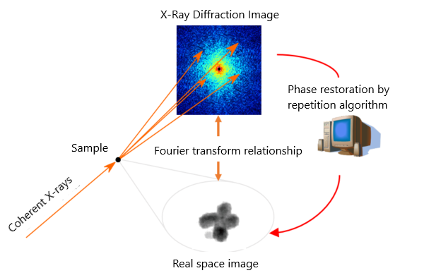
The conceptual diagram of CDI experiments
Y. Nishino et al., Phys. Rev. Lett. 102, 018101 (2009).
Basic Performance and Results
Shared equipment
The experimental equipment shared with CDI experiments, MAXIC (Multiple Application X-ray Imaging Chamber), which is used to produce optimal results, will be introduced here. At the moment, the following two latest-model devices are in operation.
MAXIC-II
This device mainly targets submicron scale samples, and it inherits the basic performance of MAXIC. The sample is illuminated with a 1 μm focusing beam and the X-ray diffraction imaging is recorded with a resolution on the order of 10 nm (q < 0.1 nm-1 @4 keV). It is also possible to perform pump-probe measurements using nanosecond optical lasers.
MAXIC-S
The focusing mirror optical system built into the device enables the sample to be illuminated with a 100 μm beam. This allows for recording X-ray diffraction images with a minimum resolution of approximately 2 nm (q < 0.5 nm-1 @4 keV).
References:
C. Song et al., J. Appl. Cryst. 47, 188 (2014).
Example measurement: Imaging living cells
Professor Nishino’s research group at Hokkaido University has developed a micro-liquid enclosure array (MLEA), and CDI experiments were conducted inside microbacterium lacticum cells. By measuring using MAXIC, visualization of the inside of living cells has been successfully performed.

CDI experiments on live microbacterium lacticum cells
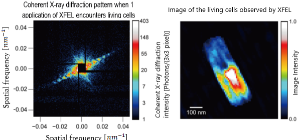
ー Coherent diffraction images obtained in CDI experiments (left) and real space images reconstructed by data analysis (right)
[ From a press release on January 7, 2014]
References:
Experimental Equipment
MAXIC-II
This device inherits the main functions of MAXIC, and has added functions for pump-probe measurements using optical lasers. The basic components of this device include two sets of 4-quadrant slits, and a sample manipulator installed in the vacuum chamber. If desired, the optical elements for pump lasers can also be laid out on an optical breadboard in the chamber.
In short, the chamber is connected to the beamline’s general purpose focusing system and measurements are performed using a micro X-ray beam. Parasitic scattered X-rays from the beamline optical systems are removed by two pairs of 4-quadrant slits in the chamber. An MPCCD detector is used to detect the diffracted X-rays from the sample.
Samples are often supported by silicon nitride thin films, or something similar, and are mounted on sample manipulators. Since the sample irradiated with the XFEL pulse is destroyed, a new sample is moved into the irradiation position each time it is irradiated. The chamber is equipped with a microscope for observing samples, and it is used to adjust the irradiation position.

MAXIC-II: Entire device

MAXIC-II: Inside the vacuum chamber
MAXIC-S
This device has a dedicated multilayer focusing mirror that can irradiate the sample with an XFEL beam with a spot size of approximately 100nm. By using a high-intensity focusing beam, it is possible to obtain a high-resolution image of the sample. In addition to the focusing mirror, two pairs of 4-quadrant slits, a sample manipulator, a microscope for sample observation, and a load-lock device for sample exchange are also equipped.
※ MAXIX-S was developed in collaboration with a group led by Professor Yoshinori Nishino at Hokkaido University. In addition, advancements have been carried out by the SACLA Infrastructure Development Program
References:
T. Koyama et al., Microsc. Microanal. 24, 294 (2018).

Detector
The coherent diffraction images are recorded by the MPCCD detector. The Octal MPCCD detector covers a wide-angle area, and the Dual MPCCD for small-angle areas are placed in tandem to record the diffraction images over a wide-angle range.
Operating Parameters (EH3 & 4b @ BL2)
CDI experiments are generally conducted on BL2 EH3&4B.
XFEL parameters
| Photon energy (Fundamental wave) | 4-20 keV |
| Pulse energy | To photon energy (See figure below) |
| Energy width(ΔE/E) | ~0.5%(Without a two crystal spectrometer) |
| Repetition rate | 30 Hz(BL2&3 Simultaneous operation) |
References:
M. Yabashi et al., J. Synchrotron Rad. 22, 477 (2015).
K. Tono et al., J. Synchrotron Rad. 26, 595 (2019).
(Reference) The relationship between photon energy and pulse energy / photon number (for BL3)
Optical laser characteristics
| Green Laser Minilite, Continuum |
Optical parametric oscillator * NT232, Ekspla |
|
| Wavelength | 532 nm | 532 nm |
| Max. Pulse Energy | ~20 µJ | wavelength dependent (see figure below) |
| Pulse Duration | 3-5 ns | 2-5 ns |
| Rep. Rate | 10 Hz | 30 Hz |
*The pulse energy of the Optical Parametric Oscillator (OPO) depends on the wavelength.
Measurement Instrument Configuration
Standard placement of the MPCCD detector
| MPCCD Octal | MPCCD Dual | |
| Sensor area | 110 mm x 110 mm | 52 mm x 52 mm |
| MAXIC-II Standard camera length |
1.5 m | 3 m(installed in EH3) 9 m(installed in EH4b) |
| MAXIC-S Camera length (fixed) |
0.32 m | 1.6 m |
Adjustments before the Measurement
What SACLA staff do before the beam time
The following tasks are performed by SACLA staff before the beam time:
- ・Bring the equipment to the experimental hutch
- ・XFEL spectrum measurements, optical axis adjustments
- ・Adjust the XFEL focusing optical systems
- ・Align the 4-quadrant slits (Coarse adjustments)
For pump-probe experiments using synchronous lasers, SACLA staff will also perform the following tasks:
- ・Adjust and focus the synchronous laser spectrum and the optical axis
- ・Rough alignment of the XFEL synchronous laser
- ・Timing adjustments of the XFEL and synchronous laser using high-speed PD
The main operations performed by the user after the start of the beam time:
In order to conduct CDI experiments, the following are the experimental operations that the user must perform.
- ・Sample exchange and associated vacuum chamber opening/closing and exhaust operation
- ・Align the 4-quadrant slits (coarse adjustments)
- ・Adjust the sample position
- ・Precise adjustments of the XFEL and synchronous laser irradiation position (in the case of pump-probe experiments)
Measurement flow
Measurement flow (for MAXIC-II)
- 1.Mount the sample on the manipulator.
- 2.Vacuum evacuation of the MAXIC-II chamber.
- 3.Align the sample with respect to the X-ray irradiation position by using the long working microscope provided in the chamber.
- 4.Set the parameters (such as the coordinates for the irradiation position) for scanning the sample.
- 5.Open the gate valve between the MAXIC-II chamber and the detector.
- 6.Start scanning the sample and recording the diffraction image by using the RunControl GUI.
- 7.Open the chamber to the atmosphere to take out the sample.
Manuals and more
SACLA measurement procedure manual download
SACLA HPC Portal site (VPN connection required)