BL3(硬X線)
BL3はSACLAにおける初めての硬X線FELビームラインです。 2012年3月の供用開始から、 様々な分野において革新的な成果をうみだしています。 自己増幅自発放射方式(Self-Amplified Spontaneous Emission : SASE)による通常の運転モードで利用できる光子エネルギーの範囲は4~20 keVで、XFELビームを輸送するためにX線ミラーと二結晶分光器のいずれかを選択して用います。BL3の特色は、通常の運転モードに加えて、2色XFELやセルフシードXFELのような先端的XFELパルスを利用できることです。実験システムとして、XFELとフェムト秒光学レーザーのタイミングモニター、XFELナノ集光光学系、ハイパワーナノ秒レーザーとXFEL同時利用実験プラットフォームなどを備えています。
参考文献:
T. Ishikawa et al., Nature Photonics, 6, 540 (2012).
K. Tono et al., New J. Phys., 15, 083035 (2013).
K. Tono et al., J. Synchrotron Rad. 26, 595 (2019).
光源性能
| 最大電子ビームエネルギー | 8.5 GeV |
| 繰り返しレート | 30 Hz(BL2&3同時運転時) |
| アンジュレータ周期長 | 18 mm |
| K値 | ~2.6 |
| 光子エネルギー(基本波) | 4-20 keV |
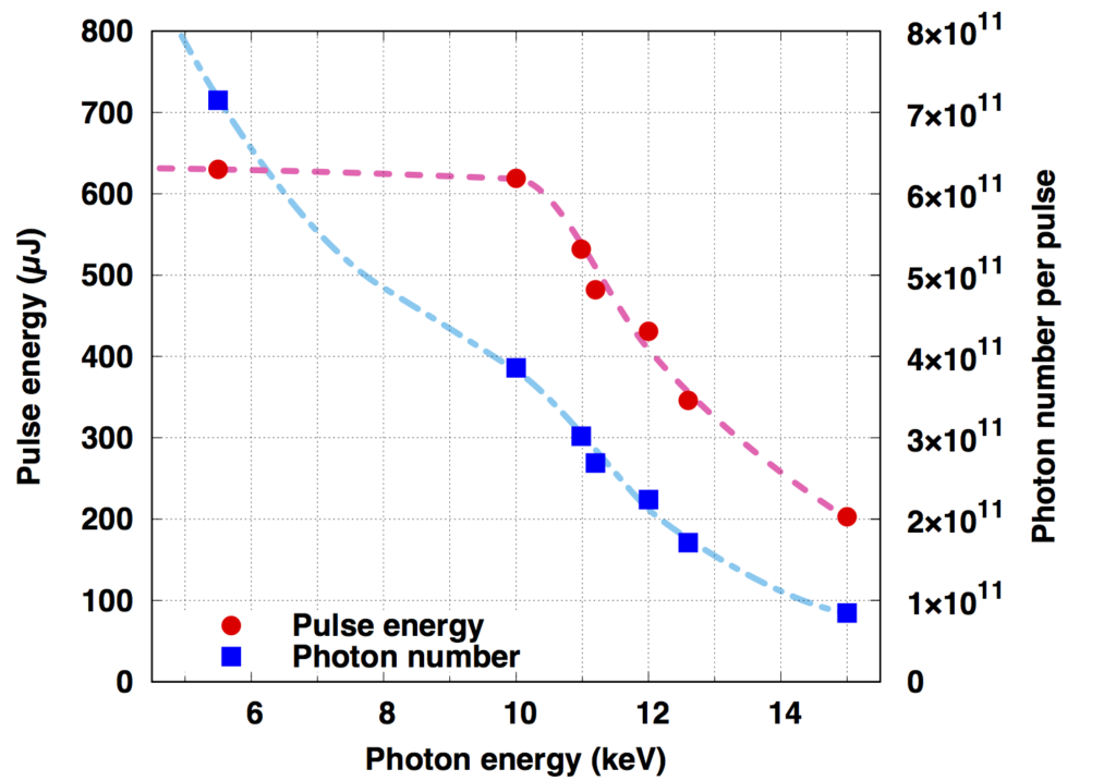
| パルスエネルギー | 光子エネルギーに依存(下図参照) |
| エネルギー幅(ΔE/E) | ~0.5%(二結晶分光器なし) ~0.01%(二結晶分光器あり) |
| パルス幅 | < 10 fs |
参考文献:
M. Yabashi et al., J. Synchrotron Rad. 22, 477 (2015).
K. Tono et al., J. Synchrotron Rad. 26, 595 (2019).
(参考)光子エネルギーとパルスエネルギー・光子数の関係(BL3の場合)
(参考)自己増幅自発放射(SASE)方式のスペクトル例
BL3の特殊運転
BL3では、通常のXFEL運転に加え、特殊なモードでの運転が可能です。各運転の概要については下記をご覧ください。
特殊運転を利用した実験を計画されている場合は、各運転の詳細情報をご確認の上、課題申請前にXFEL利用研究推進室(このメールアドレスはスパムボットから保護されています。閲覧するにはJavaScriptを有効にする必要があります。)まで必ずお問い合わせください。
2色XFEL
SACLAのアンジュレータ列を2つの区間に分けて、それぞれに異なるギャップを設定することで2種類の波長のXFELを発振させることができます。BL3においては、 1色目のレーザー発振を終えた電子ビームをマグネティックシケインにより迂回させ、1色目と2色目のXFELパルスの間に時間差を付けることが可能です。 遅延時間は数十アト秒の精度で設定することができ、精密なポンププローブ計測などへの応用が期待できます。詳しくはこちらをご覧ください。
参考文献:
T. Hara et al., Nat. Commun. 4, 2919 (2013).
2色発振時のXFELビームパラメーターの例
| 第1色 | 第2色 | |
| 光子エネルギー | 13.1 keV | 9.7 keV |
| パルスエネルギー | 40 µJ | 40 µJ |
| 最大遅延時間 | – | 300 fs |
| 第1色 | 第2色 | |
| 光子エネルギー | 12.2 keV | 9.7 keV |
| パルスエネルギー | 50 µJ | 30 µJ |
| 最大遅延時間 | – | 300 fs |
| 第1色 | 第2色 | |
| 光子エネルギー | 6.1 keV | 5.9 keV |
| パルスエネルギー | 60 µJ | 60 µJ |
| 最大遅延時間 | – | 450 fs |
セルフシードXFEL
BL3において、反射型セルフシード方式によるXFELの利用が可能です。セルフシードXFELは、SASE型XFELと同等の平均パルスエネルギーを有しつつ、高い単色性を示します。詳しくはこちらをご覧ください。
参考文献:
I. Inoue et al., Nature Photon. 13, 319 (2019).
光源パラメーター
| 光子エネルギー | 7 keV-15 keV |
| エネルギー幅 | 0.01% |
| パルスエネルギー | 200 µJ@7-10 keV, ~100 µJ@15 keV |
SDO(Split-and-Delay Optics)
BL3 OHには、分割遅延光学系(Split-and-Delay Optics, SDO)が常設されており、時間差を有するダブルパルスXFELを実験に利用できます。詳しくはこちらをご覧ください。
※SDOは、大阪大学の山内和人教授のグループとの共同開発により整備されました。
参考文献:
T. Osaka et al., IUCrJ 4, 728 (2017).
T. Hirano et al., J. Synchrotron Rad. 25, 20 (2018).
典型的なパラメータ
| Photon energy range | 5 ~ 15 keV |
| Relative bandwidth of each branch | 5.6 × 10⁻⁵ |
| Typical pulse energy of each branch | ~0.2 μJ (SASE) ~2 μJ (self-seeding) |
| Delay time range | negative to >100 ps |
| Delay time step | <1 fs |
| Pre-alignment time | ~5 hours |
=======ここから下について=====
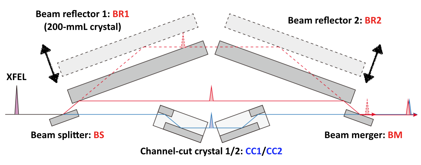
Schematic layout of the SDO system

Conceptual illustration of the wavefront splitting (left) and example beam profiles measured at the exit of the SDO system
SDOに入射されたXFELパルスは、波面分割結晶(BS)により2つに分割されます。透過側のブランチ(青)には高品質なSi(220)チャネルカット結晶2個配置されており、光路長はある光子エネルギーにおいては固定となります。反射側のブランチ(赤)はBSを含め計4つの独立したSi(220)結晶で構成されています。結晶BR1とBR2とをそれぞれ移動させることで、光路長を変えることができ、分割パルス間の到達時間差を制御できます。

Photon-energy dependence of the range of time delay. At positive delay times, the CC branch pulse comes earlier.
パルス間の時間差は0 fsをまたいで100 ps以上にまで、1 fs以下のステップで調整可能です。
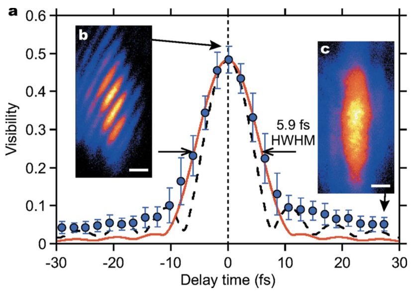
Example results of field autocorrelation measurement
正確な時間差ゼロは、干渉縞のビジビリティ変化から、数fsの精度で決定できます。ただし、干渉縞の発生には両ブランチが共に同じ光子エネルギーである必要があります。
XPR(X-ray phase retarder)
BL3 OHには、XFELの偏光を制御するためのX線移相子(X-ray phase retarder, XPR)が常設されており、偏光が制御されたXFELを実験に利用できます。詳しくはこちらをご覧ください。
参考文献:
M. Suzuki et al., J. Synchrotron Radiat. 21, 466 (2014).
Y. Kubota et al., J. Synchrotron Radiat. 26, 1139 (2019).
XPR装置の利用パラメーター例
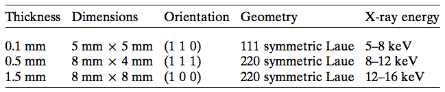
XPR装置には偏光を制御するための3種類のダイヤモンド結晶が備えられています。各ダイヤモンドのパラメータと対応する光子エネルギーを以下に示します。
各ダイヤモンド結晶を用いた際の円偏光度と透過率のX線光子エネルギー依存性の計算値は以下の通りです。
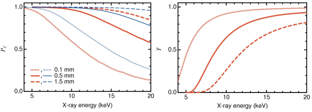
ー円偏光度(左図)と透過率(右図)の光子エネルギー依存性
11.562 keV(PtのL3殻吸収端)における垂直直線偏光度と円偏光度の測定結果はそれぞれ67%、97%です。
共通装置
BL3に常設されている下記の装置を、必要に応じて利用することができます。
インラインスペクトロメーター
全てのXFELパルスの中心光子エネルギーを記録します。
ビームモニター
全てのXFELパルスのパルスエネルギーを記録します。
チャンネルカットモノクロメーター
シリコンのチャンネルカット結晶を2つ用いたモノクロメータです。
シングルショットスペクトロメーター
全てのXFELパルスのスペクトルを記録します。分解能と観測領域が可変ですが、分解能が良くなると観測領域は狭くなります。
タイミングモニター
XFELとフェムト秒光学レーザーのタイミングを全てのパルスについて記録します。
主な実験
BL3では主に下記のような実験が実施されます。
また、下記のような実験も可能です。
BL3
BL3 is the first hard X-ray FEL beamline at SACLA. Since it’s launch in March 2012, it has produced innovative results in various fields. The range of photon energy available in normal operating modes with Self-Amplified Spontaneous Emission (SASE) is 4-20 keV, with either X-ray mirrors or double crystal spectrometers selected to transport the XFEL beams. In addition to the normal operating modes, BL3 features advanced XFEL pulses such as two-color XFEL and self-seeded XFEL. The experimental system is equipped with a timing monitor for XFEL as well as femtosecond optical lasers, an XFEL nano-focusing optical system, a high-power nanosecond laser and an XFEL simultaneous use experimental platform.
References:
T. Ishikawa et al., Nature Photonics, 6, 540 (2012).
K. Tono et al., New J. Phys., 15, 083035 (2013).
K. Tono et al., J. Synchrotron Rad. 26, 595 (2019).
Performance of the light source
| Maximum electron beam energy | 8.5 GeV |
| Repetition rate | 30 Hz(BL2&3 simultaneous use) |
| Undulator periodic length | 18 mm |
| K Value | ~2.6 |
| Photon energy (fundamental wave) | 4-20 keV |
| Pulse energy | Depends on the photon energy (see figure below) |
| Energy width(ΔE/E) | ~0.5%(without a two crystal spectrometer) ~0.01%(with a two crystal spectrometer) |
| Pulse width | < 10 fs |
References:
M. Yabashi et al., J. Synchrotron Rad. 22, 477 (2015).
K. Tono et al., J. Synchrotron Rad. 26, 595 (2019).
(Reference) The relationship between photon energy and pulse energy / photon number (For BL3)

Examples of the Self-Amplified Spontaneous Emission (SASE) method
Special operation of BL3
At BL3, in addition to normal XFEL operation, it is possible to operate in a special mode. Please see below for an overview of each operation.
If you are planning an experiment using special operation, please be sure to check the detailed information of each operation and contact the FEL Utilization Division (このメールアドレスはスパムボットから保護されています。閲覧するにはJavaScriptを有効にする必要があります。) before applying for an assignment.
2 Color XFEL
The undulator column at SACLA can be divided into two intervals, each with a different gap to oscillate XFEL at two different wavelengths. At BL3, after the electron beam has finished its laser oscillation of the first color, it can be diverted with a magnetic chicane, and a time difference can be introduced between the first and second color XFEL pulses. The delay time can be set with an accuracy of several tens of attoseconds, and it is expected to be applied to precise pump-probe measurements. Please see here here for more details.
References:
T. Hara et al., Nat. Commun. 4, 2919 (2013).
Examples of XFEL parameters during two color oscillations
| Color 1 | Color 2 | |
| Photon energy | 13.1 keV | 9.7 keV |
| Pulse energy | 40 µJ | 40 µJ |
| Maximum delay time | – | 300 fs |
| Color 1 | Color 2 | |
| Photon energy | 12.2 keV | 9.7 keV |
| Pulse energy | 50 µJ | 30 µJ |
| Maximum delay time | – | 300 fs |
| Color 1 | Color 2 | |
| Photon energy | 6.1 keV | 5.9 keV |
| Pulse energy | 60 µJ | 60 µJ |
| Maximum delay time | – | 450 fs |
Self-Seed XFEL
At BL3, it is possible to use the reflective self-seed method. Self-seed XFEL have the same average pulse energy as SASE XFEL, but exhibit high-monochromaticity. Please see here here for more details.
References:
I. Inoue et al., Nature Photon. 13, 319 (2019).
Light source parameters
| Photon energy | 7 keV-15 keV |
| Energy width | 0.01% |
| Pulse energy | 200 µJ@7-10 keV, ~100 µJ@15 keV |
SDO(Split-and-Delay Optics)
The BL3 OH is permanently equipped with Split-and-Delay Optics (SDO), which enable double pulse XFEL with time differences for experimental use. Please see here here for more details.
※ The SDO was developed in collaboration with the group led by Professor Kazuto Yamauchi at Osaka University.
References:
T. Osaka et al., IUCrJ 4, 728 (2017).
T. Hirano et al., J. Synchrotron Rad. 25, 20 (2018).
Typical parameters
| Photon energy range | 5 ~ 15 keV |
| Relative bandwidth of each branch | 5.6 × 10⁻⁵ |
| Typical pulse energy of each branch | ~0.2 μJ (SASE) ~2 μJ (self-seeding) |
| Delay time range | negative to >100 ps |
| Delay time step | <1 fs |
| Pre-alignment time | ~5 hours |
======= From here below =====

Schematic layout of the SDO system
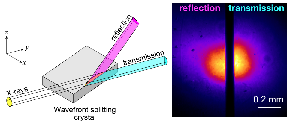
Conceptual illustration of the wavefront splitting (left) and example beam profiles measured at the exit of the SDO system
The XFEL pulses incident on the SDO are split into two by the wavefront splitting crystal (BS). Two high-quality Si (220) channel-cut crystals are arranged on the branch (blue) on the transmission side, and the optical path length is fixed for certain photon energy. The reflective branch (red) consists of four independent Si (220) crystals, including the BS. By moving the crystals BR1 and BR2, the optical path length can be changed, and the arrival time difference between the split pulses can be controlled.
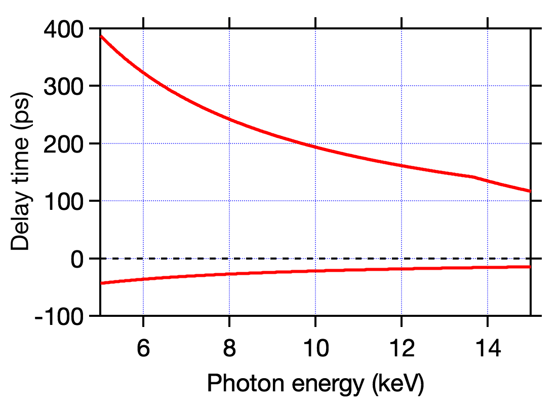
Photon-energy dependence of the range of time delay. At positive delay times, the CC branch pulse comes earlier.
The time difference between the pulses can be adjusted in steps of 1 fs or less, spanning from 0 fs to up to 100 ps or more.

Example results of field autocorrelation measurement
The exact time difference zero can be determined with an accuracy of a few fs from the visible change of the inference fringes. However, both branches must have the same photon energy for interference fringes to occur.
XPR(X-ray phase retarder)
BL3 OH is permanently equipped with an X-ray Phase Retarder (XPR) to control the polarization of the XFEL, enabling polarization controlled XFELs to be used for experiments. Please see here here for more details.
References:
M. Suzuki et al., J. Synchrotron Radiat. 21, 466 (2014).
Y. Kubota et al., J. Synchrotron Radiat. 26, 1139 (2019).
Examples of XPR device usage parameters
The XPR device is equipped with three types of diamond crystals to control polarization. The parameters of each diamond and the corresponding photon energies are shown below.

The calculated values of the X-ray photon energy dependence of the degree of circular polarization and the transmittance when using each diamond crystal are as follows:

Photon energy dependence of circular polarization (left) and transmittance (right)
The measurement results for the vertical linear degree of polarization and the circular degree of polarization at 11.562 keV(L3 shell absorption end of Pt)are 67% and 97% respectively.
Shared equipment
The following equipment is permanently installed at BL3 and can be used as needed.
Inline spectrometer
To record the central photon energy of all XFEL pulses.
Beam monitor
To record the pulse energy of all XFEL pulses.
Channel-cut monochromator
This monochromator uses two silicon channel-cut crystals.
Single shot spectrometer
This records the spectrum of all XFEL pulses. The resolution and observation area are variable, but the better the resolution, the narrower the observation area.
Timing monitor
To record the timing of all XFEL and femtosecond optical laser pulses.
Key experiments
At BL3, the following experiments are generally performed: