- 詳細
- 投稿者: Super User
- カテゴリ: 設備
- 参照数: 1572
ハイスループット粉末X線回折計
◆装置概要
多結晶など身近な材料の粉末回折測定ができます。数mgの微量の粉末試料があればデータが取れます。また、産業利用BLの特徴として、ロボットを用いた全自動測定が可能であり、さらにユーザが希望する様々な試料環境にも対応できる装置構成になっています。
◆装置の特徴
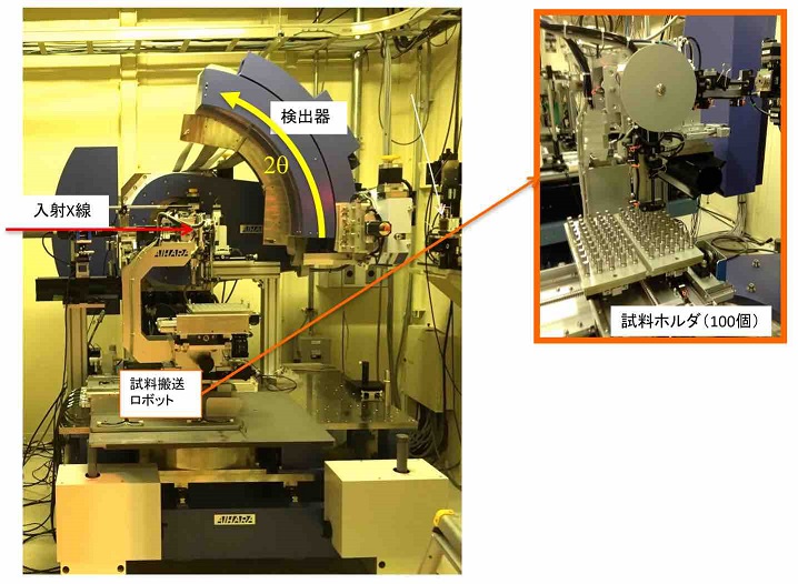
ハイスループット粉末回折装置はBL19B2の第1実験ハッチに設置されています。フォトンカウンティング型半導体1次元検出器MYTHENを回折角方向に12個並べたオリジナルの回折計です。1回の露光で回折角2θの80°の範囲を0.005°の角度分解能でカバーします。装置の制御には、コマンド入力型言語SPECに独自に開発したGUIを組み合わせたものを用いており、初心者でもすぐに実験方法を理解できるような仕組みにしています。試料交換や位置合わせなど、データ収集に関するほぼ全ての作業はロボットを利用して自動化されています。試料に照射するX線のビームサイズは縦0.3mm ×横3mmで,細いガラスキャピラリに粉末試料を充填して透過配置で測定します.利用可能なX線エネルギーは7-37 keVです.◆装置アクセサリー
ガラスキャピラリに低温あるいは高温の窒素ガスを直接吹き付けることによって試料の温度を変化させながら測定することができます。
低温装置は100-500 K、高温装置は室温-1000 Kをカバーします。これらの温度変化装置は試料交換ロボットと連携しており試料の準備さえ済めば全自動で温度変化測定のデータが得られます。
その他に、粉体化することが難しい試料に関しては、3軸同時揺動の仕組みをもつ特殊な試料ステージを用意しています。これを用いることで金属バルク試料のように結晶粒が大きいが粉末にすることが難しい試料においても、そのままの形態で結晶構造解析が可能な粉末回折プロファイルを取得することができます。
また、透過配置で実験できない平板試料についても反射配置測定でも十分に高い角度分解能のデータを収集できるマルチソーラスリットシステムを用意しています。
このようにロボットを用いた全自動測定以外にも様々な用途に利用できるように設計されていますので詳しくはビームライン担当にお尋ねください。
◆実験・試料準備
実験に用いるガラスキャピラリは試料とともにX線が照射され、それ自身からの散乱もバックグラウンドとして観測されます。
目的に応じて材質やサイズを使い分ける必要があります。
まず材質については、できる限り肉薄でX線散乱を起こしにくい「リンデマンガラス」製を基本としてお勧めします。
しかし、リンデマンガラスは高温で軟化するので、概ね500℃以上の高温実験を行う際には「ボロシリケートガラス」「ソーダガラス」「石英ガラス」製を利用してください。
最も高温に対する耐性が高いのは石英ガラス製ですが、バックグラウンドの形状が複雑になるのが欠点ですので使い分けが重要です。
キャピラリの内径は0.3 mmが標準ですが、X線吸収の影響などを加味して多少の増減を検討します。
なお、実験作業のほとんどはロボット化されているので実験進捗は試料調製に律速します。
したがって、ガラスキャピラリに粉末を充填する調製作業はあらかじめ来所前に済ませておくことをお勧めします。また、温度変化測定において試料の酸化や変質が懸念される場合はキャピラリ中を不活性ガス置換して封止するなどの対策をしてください。
粉末充填作業や試料ホルダの取り扱い方法については以下のURL内の動画の前半部分を参考にしてください。
https://support.spring8.or.jp/powder/jukebox.html
◆実験手順・注意事項
ロボットを用いた全自動測定では、
まず、ガラスキャピラリに粉末が充填されている状態のものを装置専用の試料ホルダに取り付けます。
扱いやすい取り付け治具を用意しているので1個あたり1-2分で準備完了です。
試料ホルダは最大100個までロボットに搭載できます。
試料の選択や露光条件はMicrosoft Excelのシートに入力します。
統計精度の高い精密なデータを得る条件を算出するために1試料1〜数分のスクリーニング測定をお勧めします。
この結果を見て、行いたい解析に対して十分な統計精度のデータを得るための露光条件(露光時間)を検討します。
また,必要に応じてガラスキャピラリのみ(ブランク)のデータを測定しておくといいでしょう。
ガス吹付による温度変化測定を行う際には露光時間に加えてガスの温度変化ならびに試料の温度安定に要する時間も考慮しなければなりません。
温度変化を含む測定には点数や変化速度にも依りますが室温のみの測定の2〜数倍の時間を要します。
また、温度変化に関しては、過冷却や過熱が試料の状態に影響を与える場合には、オーバーシュートを起こさないような変化速度を設定します。
これらの装置の条件も,Microsoft Excelのシートに入力することで制御できます.
◆問い合わせ先
大坂 恵一 このメールアドレスはスパムボットから保護されています。閲覧するにはJavaScriptを有効にする必要があります。
◆代表的な論文リスト
“New perovskite-related structure family of oxide-ion conducting materials NdBaInO4”
K. Fujii, Y. Esaki, K. Omoto, M. Yashima, A. Hoshikawa, T. Ishigaki, and J. R. Hester
Chem. Mater., 26, 8, (2014) 2488–2491
DOI:10.1021/cm500776x
“Quantitative analysis of heavy elements and semi-quantitative evaluation of heavy mineral compositions of sediments in Japan for construction of a forensic soil database using synchrotron radiation X-ray analyses”
I. Nakai, S. Furuya, W. Bong, Y. Abe, K. Osaka, T. Matsumoto, M. Itou, A. Ohta and T. Ninomiya
X-ray spectrometry 43, (2014) 38-48
DOI : 10.1002/xrs.2496
"Effect of Annealing on Crystal and Local Structures of Doped Zirconia Using Experimental and Computational Methods"
T. Itoh, M. Mori, M. Inukai, H. Nitani, T. Yamamoto, T. Miyanaga, N. Igawa, N. Kitamura, N. Ishida, and Y. Idemoto
The Journal of Physical Chemistry C 119 (16), (2015) 8447-8458
DOI:10.1021/jp5117118
"Crystalline-Amorphous-Crystalline Transformation in a Highly Brilliant Luminescent System with Trigonal-Planar Gold(l) Centers"
K. Igawa, N. Yoshinari, M. Okumura, H. Ohtsu, M. Kawano and T. Konno
Scientific Reports 6, (2916) 26002
DOI:10.1038/srep26002
"Versatile High-Throughput Diffractometer for Industrial Use at BL19B2 in SPring-8"
K. Osaka, Y. Yokozawa, Y. Torizuka, Y. Yamada, M. Manota, N. Harada, Y. Chou, H. Sasaki, A. Bergamaschi, and Masugu Sato
AIP Conference Proceedings 2054, (2019) 050008
DOI : 10.1063/1.5084626
High-Throughput X-Ray Powder Diffractometer
◆Equipment overview
It is possible to obtain powder diffraction measurements of materials such as polycrystals. Data can be obtained with a small amount of trace mg powder samples. In addition, a feature of the industrial use BLs is a robot that is available to make fully automated measurements, and the device configurating is compatible with many sample environments desired by the user.

◆Features of the Equipment
A high-throughput powder diffractometer is installed in the BL19B2 beamline’s first experimental hatch. MYTHEN, an original photon counting, 1-dimensional semiconductor detector, is arranged in 12 pieces in the angle equal to the diffraction angle. One exposure covers a 2θ diffraction angle of a range of 80°, and a resolution angle of 0.005°. To control the device, an original GUI has been developed for the input language SPEC, and is straight forward to allow first-time users to immediately understand the experimental methods. Almost all data collection operations, such as sample exchanges and sample positioning, are automatically completed using robots. While the sample is being irradiated by the X-rays, the beam size has a length of 0.3mm and a width of 3mm, and through a thin, glass capillary, the powder samples can be measured. The available X-ray energy is 7-37keV.◆Equipment accessories
By spraying a glass capillary with low or high temperature Nitrogen gas, the temperature of the sample changes and can be measured while changing.
The low temperature devices cover 100 to 500K, and the high-temperature devices cover everything from room temperature to 1000K. The temperature change devices are linked with the sample exchange robot, and once the sample is prepared, the temperature change measurement data can be obtained fully automatically.
In addition, for samples that are difficult to powder, a special sample stage with a three-axis simultaneous shake mechanism is available. This can be used for difficult to powder samples, such as bulk metal samples with large crystal grains, to obtain powder diffraction profiles that can be used to analyze the crystal structure.
In addition, for reflection arrangement measurements on flat plate samples that cannot be tested with transmission arrangements, a multi-solar slit system can collect data with very high angular resolution.
This such robot is designed to be used for various purposes other than fully automated measurements. Please ask the person in charge of the beamline for more information.
◆Experiment / sample preparation
During the experiment, the glass capillary and the sample are both irradiated with X-rays, and the background scattering is observed.
It is necessary to use different materials and size depending on the objective of the experiment.
First, it is recommended that the material be made of “Lindeman Glass”, which is thin and limits X-ray scattering.
However, Lineman glass becomes soft at high temperatures so for experiments above 500℃, please use “borosilicate glass”, “soda glass” or “quartz glass”.
Quartz glass has the highest temperature resistance, but the disadvantage is that the shape of the background is complex, so its use should be contemplated carefully.
The standard inner diameter of the capillary is 0.3mm, but increases and decreases under the influence of X-ray absorption.
In addition, since most of the experiment is completed by a robot, the progress of sample preparation is done quickly.
Therefore, it is recommended that the preparation work for filling the glass capillaries with powder be completed before coming to the office. Consequently, it is recommended that the preparation work of filling the glass capillary with powder be completed before entering the office. Also, if there is a concern about sample oxidation or deterioration while taking temperature change measurements, the capillary should be filled with inert gas or sealed.
For information on powder filling and operation of the sample holder, please refer to the first half of the video in the URL below.
https://support.spring8.or.jp/powder/jukebox.html
◆Experimental procedure / precautions
With fully automated measurements using the robot, first fill the capillary with powder, then attach to the sample holder dedicated to the device.
Easy-to-handle mounting jigs are available, which can each be assembled within 1-2 minutes.
Up to 100 sample holders can be mounted to a single robot.
Sample selection and exposure conditions are entered into a Microsoft Excel spreadsheet.
It is recommended that screening measurements of 1 minute per 1 sample is used to obtain high precision data with high statistical accuracy.
By looking at this result, you can determine the exposure conditions (exposure time) to obtain sufficient statistical accuracy for the data analysis you wish to perform.
Also, if necessary, glass capillary data (empty) should be measured.
When measuring temperature changes due to gas spraying, exposure time, the sample’s temperature stability and the time for the gas to change temperature should all be accounted for.
Temperature change measurements take at least 2 times longer than room temperature measurements, since they rely on several points to determine the rate of change.
In addition, for temperature changes, if overcooling or overheating affects the condition of the sample, it is possible to set a change rate so overshooting does not occur.
The conditions of these devices can also be controlled by entering them in a Microsoft Excel sheet.
◆Contact
大坂 恵一 このメールアドレスはスパムボットから保護されています。閲覧するにはJavaScriptを有効にする必要があります。
◆List of representative treatises
“New perovskite-related structure family of oxide-ion conducting materials NdBaInO4”
K. Fujii, Y. Esaki, K. Omoto, M. Yashima, A. Hoshikawa, T. Ishigaki, and J. R. Hester
Chem. Mater., 26, 8, (2014) 2488?2491
DOI:10.1021/cm500776x
“Quantitative analysis of heavy elements and semi-quantitative evaluation of heavy mineral compositions of sediments in Japan for construction of a forensic soil database using synchrotron radiation X-ray analyses”
I. Nakai, S. Furuya, W. Bong, Y. Abe, K. Osaka, T. Matsumoto, M. Itou, A. Ohta and T. Ninomiya
X-ray spectrometry 43, (2014) 38-48
DOI : 10.1002/xrs.2496
"Effect of Annealing on Crystal and Local Structures of Doped Zirconia Using Experimental and Computational Methods"
T. Itoh, M. Mori, M. Inukai, H. Nitani, T. Yamamoto, T. Miyanaga, N. Igawa, N. Kitamura, N. Ishida, and Y. Idemoto
The Journal of Physical Chemistry C 119 (16), (2015) 8447-8458
DOI:10.1021/jp5117118
"Crystalline-Amorphous-Crystalline Transformation in a Highly Brilliant Luminescent System with Trigonal-Planar Gold(l) Centers"
K. Igawa, N. Yoshinari, M. Okumura, H. Ohtsu, M. Kawano and T. Konno
Scientific Reports 6, (2916) 26002
DOI:10.1038/srep26002
"Versatile High-Throughput Diffractometer for Industrial Use at BL19B2 in SPring-8"
K. Osaka, Y. Yokozawa, Y. Torizuka, Y. Yamada, M. Manota, N. Harada, Y. Chou, H. Sasaki, A. Bergamaschi, and Masugu Sato
AIP Conference Proceedings 2054, (2019) 050008
DOI : 10.1063/1.5084626
- 詳細
- 投稿者: Super User
- カテゴリ: 設備
- 参照数: 717
全散乱計測装置
◆装置概要
この装置はブラッグ反射と散漫散乱の同時計測、つまり全散乱計測を前提に設計されています。一度の測定で、広い逆空間レンジ(散乱ベクトルの大きさQの最大値:30 Å-1)を高精細(Qのステップ:10-3 Å-1)かつ高S/N比(検出器のダイナミックレンジ:105~106)でカバーできるため、数Åの短距離秩序から数千Åの長距離秩序までの構造情報がシームレスに得られます。
◆装置の特徴
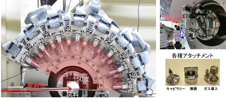
実験ハッチには、一次元光子計数型検出器システム“OHGI” (Overlapped High-Grade Intelligencer)1,2)を搭載した二軸粉末回折計が常設されています。このOHGIでは、2θ=0.5°から153°までを0.01°ステップで同時にデータを測定することができます。あらかじめ実験条件(X線エネルギーと検出器のエネルギー閾値)に合わせて検出器の感度ムラを補正することで、常時、光子計数型のダイナミックレンジを最大限活用した全散乱データを提供します3)。1) K. Kato et al., J. Synchrotron Rad. 26, 762-773 (2019).
https://doi.org/10.1107/S1600577519002145
2) 加藤 健一, 日本結晶学会誌 62, 26-34 (2020).
https://doi.org/10.5940/jcrsj.62.26
3) K. Kato et al., J. Synchrotron Rad. 27, 1172-1179 (2020).
https://doi.org/10.1107/S1600577520008929
◆装置アクセサリー
・窒素吹付低温装置(-180~200℃)
・窒素吹付高温装置(室温~800℃)
◆実験・試料準備
事前に試料をガラスキャピラリーに詰めて持参することを推奨します。キャピラリーのサイズは試料の組成や使用するX線エネルギーとも関係しますので、事前にご相談ください。
◆実験手順・注意事項
実験手順は一般的な粉末回折実験と同様です。ただ、どのような構造情報を得たいかによって測定時間が大きく異なりますので、事前にご相談ください。
◆問い合わせ先
加藤 健一 (このメールアドレスはスパムボットから保護されています。閲覧するにはJavaScriptを有効にする必要があります。)
◆代表的な論文リスト
“A statistical approach to correct X-ray response non-uniformity in microstrip detectors for high-accuracy and high-resolution total-scattering measurements”
K. Kato, Y. Tanaka, M. Yamauchi, K. Ohara, and T. Hatsui
J. Synchrotron Rad., 26, (2019) 762-773
https://doi.org/10.1107/S1600577519002145
“Nematic-to-columnar mesophase transition by in situ supramolecular polymerization”
K. Yano, Y. Itoh, F. Araoka, G. Watanabe, T. Hikima, and T. Aida
Science, 363, (2019) 161-165
https://doi.org/10.1126/science.aan1019
“Self-assembly of lattices with high structural complexity from a geometrically simple molecule”
H. Yamagishi, H. Sato, A. Hori, Y. Sato, R. Matsuda, K. Kato, and T. Aida
Science, 361, (2018) 1242-1246
https://doi.org/10.1126/science.aat6394
“Multielectron‐Transfer‐based Rechargeable Energy Storage of Two‐Dimensional Coordination Frameworks with Non‐Innocent Ligands”
K. Wada, K. Sakaushi, S. Sasaki, and H. Nishihara
Angew. Chem. Int. Ed., 57, (2018) 8886-8890
https://doi.org/10.1002/anie.201802521
“Rational synthesis of organic thin films with exceptional long-range structural integrity”
N. Seiki, Y. Shoji, T. Kajitani, F. Ishiwari, A. Kosaka, T. Hikima, M. Takata, T. Someya, and T. Fukushima
Science, 348, (2015) 1122-1126
https://doi.org/10.1126/science.aab1391
Total Scattering Measurement System
◆Equipment overview
The system is designed to take total scattering measurements through simultaneous measurements of Bragg and diffuse scattering.
In one measurement, a reciprocal space (Maximum magnitude of the scattering vector, Q: 30 Å-1), high definition (Q Step: 10-3 Å-1), and high S/N ratio (Dynamic range of the detector: 105~106) can be obtained. Therefore, structural information from short-range methods of several Å to long-ranged methods of several thousand Å can be obtained seamlessly.

◆Features of the Equipment
The experimental hatch has a biaxial powder diffractometer permanently installed, with a one-dimensional photon counting detector system “OHGI”(Overlapped High-Grade Intelligencer)1,2) equipped.OHGI has the ability to measure data from 2θ=0.5°to 153° in 0.01°simultaneous steps. By correcting the non-uniformity of the sensitivity of the detector according to the experimental conditions (X-ray energy and the energy threshold of the detector), full scattering data is provided that maximizes the dynamic range of the photon counting 3).
1) K. Kato et al., J. Synchrotron Rad. 26, 762-773 (2019).
https://doi.org/10.1107/S1600577519002145
2) K. Kato et al., Crystallographic Society of Japan 62, 26-34 (2020).
https://doi.org/10.5940/jcrsj.62.26
3) K. Kato et al., J. Synchrotron Rad. 27, 1172-1179 (2020).
https://doi.org/10.1107/S1600577520008929
◆Equipment accessories
・Low-temperature Nitrogen Spraying Device (-180~200℃)
・High-temperature Nitrogen Spraying Device (Room Temperature ~ 800℃)
◆Experiment / sample preparation
It is recommended that the sample be brought to the experiment inside a glass capillary. The size of the capillary depends on the composition of the sample as well as the energy of the X-rays used, so please contact us in advance for all of the necessary information.
◆Experimental procedure / precautions
The experimental procedure is similar to the procedure for a typical powder diffraction experiment. However, the measurement time varies depending on the structural information you wish to obtain, so please consult us in advance.
◆Contact
加藤 健一 (このメールアドレスはスパムボットから保護されています。閲覧するにはJavaScriptを有効にする必要があります。)
◆List of representative treatises
“A statistical approach to correct X-ray response non-uniformity in microstrip detectors for high-accuracy and high-resolution total-scattering measurements”
K. Kato, Y. Tanaka, M. Yamauchi, K. Ohara, and T. Hatsui
J. Synchrotron Rad., 26, (2019) 762-773
https://doi.org/10.1107/S1600577519002145
“Nematic-to-columnar mesophase transition by in situ supramolecular polymerization”
K. Yano, Y. Itoh, F. Araoka, G. Watanabe, T. Hikima, and T. Aida
Science, 363, (2019) 161-165
https://doi.org/10.1126/science.aan1019
“Self-assembly of lattices with high structural complexity from a geometrically simple molecule”
H. Yamagishi, H. Sato, A. Hori, Y. Sato, R. Matsuda, K. Kato, and T. Aida
Science, 361, (2018) 1242-1246
https://doi.org/10.1126/science.aat6394
“Multielectron‐Transfer‐based Rechargeable Energy Storage of Two‐Dimensional Coordination Frameworks with Non‐Innocent Ligands”
K. Wada, K. Sakaushi, S. Sasaki, and H. Nishihara
Angew. Chem. Int. Ed., 57, (2018) 8886-8890
https://doi.org/10.1002/anie.201802521
“Rational synthesis of organic thin films with exceptional long-range structural integrity”
N. Seiki, Y. Shoji, T. Kajitani, F. Ishiwari, A. Kosaka, T. Hikima, M. Takata, T. Someya, and T. Fukushima
Science, 348, (2015) 1122-1126
https://doi.org/10.1126/science.aab1391
- 詳細
- 投稿者: Super User
- カテゴリ: 設備
- 参照数: 616
時分割PDF解析装置
◆装置概要
大面積2次元検出器を利用し、広いQ範囲のデータを短時間で収集することができ、秒・分オーダーのPDF構造解析を行うことができます。マイクロウェーブ合成装置を用いた水熱合成環境下のPDF解析も可能です。
◆装置の特徴
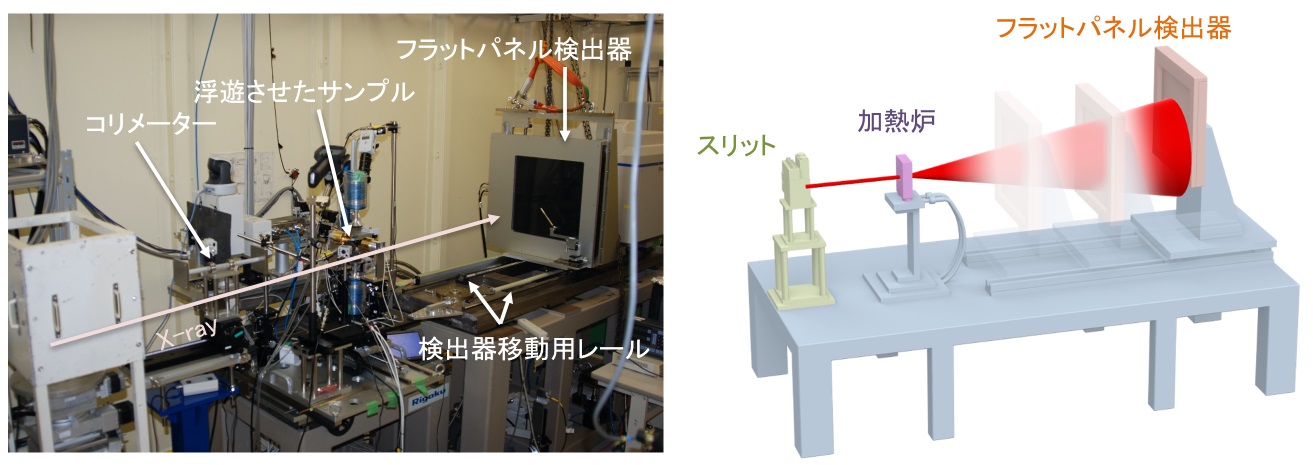
カメラ長可変架台LMガイドを敷設した架台に検出器を設置しています。300 ~ 1,000 mmの範囲でカメラ長を変更し、目的に合わせたQ範囲、Q分解能のPDF解析データを取得することが可能です。(Qmax, dQ: 25, 0.02 Å-1 @カメラ長300 mm、Qmax, dQ: 12, 0.01 Å-1 @カメラ長800 mm、)
検出器
Varex社製フラットパネル検出器XRD1621 AN3が用意されています。
スペックは、下記の通りです。
材質 単層a-Si
検出面グレード CTグレード 不良1%以下
画素ピッチ 200µm
画素数 2048×2048ピクセル
検出エリア 409.6×409.6mm2
露光時間 66.6~999ms
シンチレータ CsI
寸法 672×599×44mm
重量 25kg
制御ソフトウェア
JASRIにて製作したGUI中心の制御となっています。
◆装置アクセサリー
高温電気炉(リガク製、室温〜1,100℃)
ガス浮遊炉(800〜3,000℃)
窒素吹きかけ式低温装置(オックスフォード製:Cryojet5、-196℃〜室温)
マイクロウェーブ合成装置(バイオタージ製、室温〜300℃、20bar)
◆実験・試料準備
試料容器としては、肉厚の薄いX線回折試料用キャピラリーがお勧めです。
(例えば、オーバーシーズ・エックスレイ・サービス製:http://www.oxs.co.jp)
内径2 ~ 3 mm程度のサイズのものがよく使われます。
また、室温実験の場合、バックグラウンドを抑えたポリイミドチューブ
(K-NEX製:http://www.kei-nex.com/process.html#pageLink01)も使われます。
試料をキャピラリーに充填し封止されて持ち込まれる場合、10-2Pa程度の真空度でリークチェックを事前にお願いします。
◆実験手順・注意事項
1.標準試料CeO2を試料マウント位置にセットし、X線を照射し2次元の回折像を取得します。
2.回折像を1次元化し、CeO2の既知結晶構造からカメラ長を算出します。
3.カメラ長を算出した後、測定したい試料をセットします。
4.ビームストップにカウンターが搭載されているため、サンプルの吸収によりサンプル位置を決めます。X方向(X線と直行する方向をXとしています)のスキャンを±2mmの範囲で行い、強度が最小となるXの値に調整します。
5.サンプルの位置出しが終了したら、本測定を開始します。本測定を開始する際には、検出器のオフセット測定(X線を照射せずにデータ取得しオフセット値として記憶させる測定)を、本測定と同じ条件で実施願います。
◆問い合わせ先
尾原 幸治(このメールアドレスはスパムボットから保護されています。閲覧するにはJavaScriptを有効にする必要があります。)
山田 大貴(このメールアドレスはスパムボットから保護されています。閲覧するにはJavaScriptを有効にする必要があります。)
◆代表的な論文リスト
"Geometrical Frustration of B-H Bonds in Layered Hydrogen Borides Accessible by Soft Chemistry"
Satoshi Tominaka, Ryota Ishibiki, Asahi Fujino, Kohsaku Kawakami, Koji Ohara, Takuya Masuda, Iwao Matsuda, Hideo Hosono, and Takahiro Kondo
Chem, 6, (2020) 406-418
DOI : 10.1016/j.chempr.2019.11.006
"Controlled Growth of SrxBa1−xNb2O6 Hopper‐ and Cube‐Shaped Nanostructures by Hydrothermal Synthesis"
Ola G. Grendal, Inger‐Emma Nylund, Anders B. Blichfeld, Satoshi Tominaka, Koji Ohara, Sverre M. Selbach, Tor Grande, and Mari‐Ann Einarsrud
Chemistry - A European Journal, 26, (2020) 9348-9355
DOI : 10.1002/chem.202000373
"In-situ Phase Identification of Crystallized Compound from 2CaO·SiO2–3CaO·P2O5 Liquid"
Masanori Suzuki, Sho Nakano, Honami Serizawa, and Norimasa Umesaki
ISIJ International, 60, (2020) 1127-1134
DOI : 10.2355/isijinternational.ISIJINT-2019-449
"Observation of Liquid Phase Synthesis of Sulfide Solid Electrolytes Using Time‐Resolved Pair Distribution Function Analysis"
Koji Ohara, Naoya Masuda, Hiroshi Yamaguchi, Atsushi Yao, Satoshi Tominaka, Hiroki Yamada, Satoshi Hiroi, Masakuni Takahashi, Kentaro Yamamoto, Toru Wakihara, Yoshiharu Uchimoto, Futoshi Utsuno, and Shigeru Kimura
Physica Status Solidi B, (2020) Online publication 9 June 2020
DOI : 10.1002/pssb.202000106
"Structural Evolution of Amorphous Precursors toward Crystalline Zeolites Visualized by an in Situ X-ray Pair Distribution Function Approach"
Hiroki Yamada, Satoshi Tominaka, Koji Ohara, Zhendong Liu, Tatsuya Okubo, and Toru Wakihara
The Journal of Physical Chemistry C, 123, (2019) 28419-28426
DOI : 10.1021/acs.jpcc.9b07232
Time-Resolved PDF Analysis Equipment
◆Equipment overview
Using a large area 2-dimensional detector, data in a wide Q range can be collected in second and minute orders for PDF structural analysis. Microwave synthesis equipment is also used to make PDF analysis possible in hydrothermal synthesis environments.

◆Features of the Equipment
Variable Length Mounted CameraA detector is installed at the LM Guide stand. It is possible to change the camera length from 300 – 1,000mm, to obtain PDF analysis with a wide Q range and Q resolution to suit the experiment objective. (Qmax, dQ: 25, 0.02 A-1 @Camera Length 300 mm、Qmax, dQ: 12, 0.01 A-1 @Camera Length 800 mm)
Detector
The Flat Panel Detector XRD1621 AN3 manufactured by Varex is available.
The specifications are as follows:
Material: Amorphous Si single layer
Detection Surface Grade: CT Grade, defect rate of less than 1%
Pixel Pitch: 200μm
Number of Pixels: 2048×2048 Pixels
Detection Area: 409.6×409.6mm2
Exposure Time: 66.6~999ms
Scintillator: CsI
Dimensions: 672×599×44mm
Weight: 25kg
Control Software
This software is controlled by a GUI and was created by JASRI.
◆Equipment accessories
High Temperature Electric Furnace (Manufactured by Rigaku: room temperature to 1,100℃)
Gas Suspension Furnace (800℃ to 3,000℃)
Low Temperature Nitrogen Spraying Device (Manufactured by Oxford: Cryojet 5, -196℃ to Room Temperature)
Microwave Synthesis Equipment (Manufactured by Biotage, from room temperature to 300℃, 20bar)
◆Experiment / sample preparation
For thin X-ray diffraction samples, a capillary is recommended for the sample container.
(One example is manufactured by Overseas X-Ray Service: http://www.oxs.co.jp )
Sizes with inner diameter between 2-3mm are often used.
Also, for room temperature experiments, a background suppressing polyimide tube is also used (manufactured by K-NEX: http://www.kei-nex.com/process.html#pageLink01).
After filling the capillary with the sample and sealing, in advance to bringing the sample to the experiment, please perform a vacuum leak test to an approximate degree of 10-2Pa.
◆Experimental procedure / precautions
1.Set the standard CeO2 sample at the sample mount location, X-ray irradiation is then used to obtain a two-dimensional diffraction image.
2.The one-dimensional diffraction image can be calculated by knowing the CeO2 crystal structure and the camera length.
3.After calculating the camera length, set the sample you wish to measure.
4.The beam stop is equipped with a counter, so the sample location is decided by absorbing the sample. Scan the X direction (The X direction is the direction the X-rays are travelling) within a ±2mm range, then adjust X to the value of minimal intensity.
5.When the sample is properly positioned, start this measurement. When beginning this measurement, please perform an offset measurement of the detector (a measurement that acquires data without X-rays irradiation and stores it as an offset value) under the same conditions as the measurement.
◆Contact
尾原 幸治(このメールアドレスはスパムボットから保護されています。閲覧するにはJavaScriptを有効にする必要があります。)
山田 大貴(このメールアドレスはスパムボットから保護されています。閲覧するにはJavaScriptを有効にする必要があります。)
◆List of representative treatises
"Geometrical Frustration of B-H Bonds in Layered Hydrogen Borides Accessible by Soft Chemistry"
Satoshi Tominaka, Ryota Ishibiki, Asahi Fujino, Kohsaku Kawakami, Koji Ohara, Takuya Masuda, Iwao Matsuda, Hideo Hosono, and Takahiro Kondo
Chem, 6, (2020) 406-418
DOI : 10.1016/j.chempr.2019.11.006
"Controlled Growth of SrxBa1?xNb2O6 Hopper‐ and Cube‐Shaped Nanostructures by Hydrothermal Synthesis"
Ola G. Grendal, Inger‐Emma Nylund, Anders B. Blichfeld, Satoshi Tominaka, Koji Ohara, Sverre M. Selbach, Tor Grande, and Mari‐Ann Einarsrud
Chemistry - A European Journal, 26, (2020) 9348-9355
DOI : 10.1002/chem.202000373
"In-situ Phase Identification of Crystallized Compound from 2CaO・SiO2?3CaO・P2O5 Liquid"
Masanori Suzuki, Sho Nakano, Honami Serizawa, and Norimasa Umesaki
ISIJ International, 60, (2020) 1127-1134
DOI : 10.2355/isijinternational.ISIJINT-2019-449
"Observation of Liquid Phase Synthesis of Sulfide Solid Electrolytes Using Time‐Resolved Pair Distribution Function Analysis"
Koji Ohara, Naoya Masuda, Hiroshi Yamaguchi, Atsushi Yao, Satoshi Tominaka, Hiroki Yamada, Satoshi Hiroi, Masakuni Takahashi, Kentaro Yamamoto, Toru Wakihara, Yoshiharu Uchimoto, Futoshi Utsuno, and Shigeru Kimura
Physica Status Solidi B, (2020) Online publication 9 June 2020
DOI : 10.1002/pssb.202000106
"Structural Evolution of Amorphous Precursors toward Crystalline Zeolites Visualized by an in Situ X-ray Pair Distribution Function Approach"
Hiroki Yamada, Satoshi Tominaka, Koji Ohara, Zhendong Liu, Tatsuya Okubo, and Toru Wakihara
The Journal of Physical Chemistry C, 123, (2019) 28419-28426
DOI : 10.1021/acs.jpcc.9b07232
- 詳細
- 投稿者: Super User
- カテゴリ: 設備
- 参照数: 618
大容量高圧発生装置(SPEED-1500)
◆装置概要
大容量試料(~mm3)を約30GPaまで加圧&加熱できます。高圧高温環境下でのXRD測定、X線吸収像の観察のほか、弾性波速度や電気抵抗率などの物性測定も可能です。
◆装置の特徴
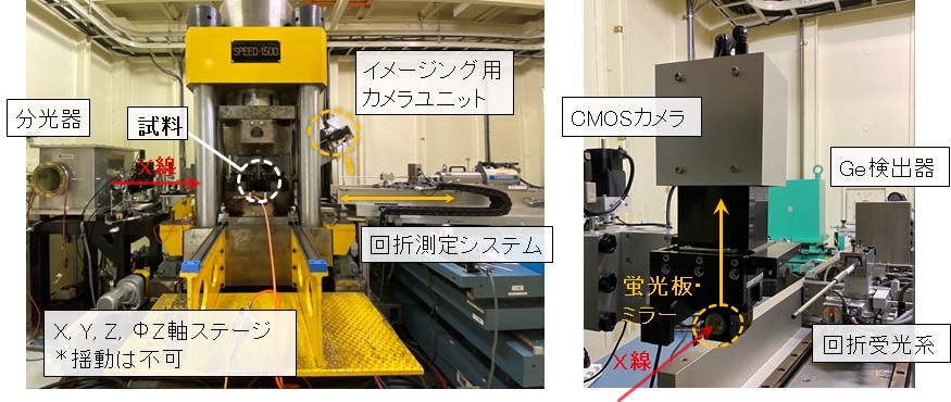
本システムは、比較的大型の試料(~mm3)を多軸圧縮で準静水圧環境下に晒すことができます。また、高圧セル内部の抵抗ヒーターで安定的に加熱できることから、高圧新奇物質のその場合成に適しています。高圧高温状態の試料に白色X線をそのまま照射して、X線吸収像の観察やXRD計測がおこなえることから、高圧相の相転移境界の決定、バルク試料の物性測定が可能です。高圧プレス
本装置は2段押しの川井型高圧発生装置であり、最大1500トンの荷重を試料に加えることができます。1軸油圧ラムとDIA型ガイドブロックを組み合わせて、荷重を6方向に分割して、高圧セルを均等に加圧できます。2段目に超硬合金製アンビル使用すると最大30 GPa程度の高圧発生が可能です。高圧セル内部に抵抗加熱式ヒーターを組み込むことで3000℃までの加熱が可能です。
X線ビームモニター
X線吸収像の観察には浜松ホトニクス製のX線ビームモニターを使用しています。GAGG蛍光板で可視光に変換し、汎用のカメラ用光学レンズで結像します。カメラは同じく浜松ホトニクス製の科学計測用のsCMOSカメラを使用しています。見かけの分解能は約3μm/pixとなります。
Ge-SSD
XRD計測にはエネルギー分散型のX線回折法を採用してします。回折X線のエネルギースペクトル測定にはミリオンテクノロジーズ・キャンベラ社製のGe-SSDを常設しており、測定可能なエネルギー範囲は10~150keVです。
◆装置アクセサリー
上記の高圧プレスで加熱するための、交流電源(2kW)と直流電源(1.6kW×2)を備えており、小型ヒーターに大電流(~300A)を印可して試料を数千度まで加熱できます。
これらのX線計測機器の他に、試料の弾性波速度(弾性率)を測定するための超音波エコー測定システムや、4端子法で電気抵抗測定が可能なデジタルマルチメーターがある。
◆実験・試料準備
基本的に一段目アンビルには一辺50mmのハイス鋼製アンビルを使用し、二段目アンビルには一辺26mmの超硬製アンビルを使用します。焼結ダイヤモンド製二段目アンビルは、より高精度のアンビル面間距離の調整が可能なSPEED-MkⅡの使用を推奨します。トランケーションサイズ(TEL)は3~12mmの範囲が一般的ですが、TELが8mm以上ではX線吸収が非常に大きいため、ガスケットにボロン製のX線窓準備したほうがよい。
一般的なスリットサイズで2θ=6°の場合、回折領域は約1mmであり、試料径は1mm以上が望ましい。試料径がそれ以下の場合は試料以外のX線回折ピークが混入する。
高圧セルを組み立てた後は十分に乾燥させ、デシケーターで保管する。
◆実験手順・注意事項
実験手順の詳細はBL担当者にお聞きください。
一般的な実験手順として、
(1)高圧セル、試料準備
希望する圧力・温度・酸素雰囲気等により高圧セルを設計、パーツを製作する。試料は粉体のペレットもしくは焼結体を用意する。
(2)装置校正
Ge-SSDのエネルギー校正、水平ゴニオメーターの2θ補正をおこなう。
(3)高圧セル設置&常圧測定
加圧前の試料の状態をX線ラジオグラフィーで確認し、XRDデータを取得する。常圧データはその後の高圧データを定量的に議論する際に非常に重要であり、圧力の計算にも欠かせない。
(4)加圧&圧力測定
大型プレスで高圧セルを加圧する。通常3~5ton/minでゆっくり加圧する。加圧中に高圧セル内の圧力標準物質のXRD測定によって得られる結晶格子の縮みから発生圧力を計算し、目標圧力に達するまで、加圧&圧力測定を繰り返す。通常数時間はかかる。
(5)加熱&データ測定
目標圧力に達した後に、内部ヒーターによる加熱を開始する。加圧によるヒーター変形があるため、ヒーターの安定性に注視しつつ、目標温度まで加熱する。昇温しつつ試料のXRDデータを取得して、相変化や格子定数変化をその場観察する。
圧力―温度平面上で多数のデータを取得する場合は(4)~(5)を繰り返す。
チェ―ブロックによる高圧セルの設置の際や、大型プレスの操作時は重大事故につながる恐れがあるため、特に注意が必要です。
また、白色X線は照射物を著しく損傷させます。X線の軸上に不用意にケーブルや検出器等を設置しないようにお願いします。
◆問い合わせ先
肥後祐司 このメールアドレスはスパムボットから保護されています。閲覧するにはJavaScriptを有効にする必要があります。
丹下慶範 このメールアドレスはスパムボットから保護されています。閲覧するにはJavaScriptを有効にする必要があります。
◆代表的な論文リスト
Formation of bridgmanite-enriched layer at the top lower-mantle during magma ocean solidification
L. Xie, A. Yoneda, D. Yamazaki, G. Manthilake, Y. Higo, Y. Tange, N. Guignot, A. King, M. Scheel & D. Andrault
Nature Communications 28 Jan. 2020:
Vol. 11, no. 548.
DOI: 10.1038/s41467-019-14071-8
Sound velocity of CaSiO3 perovskite suggests the presence of basaltic crust in the Earth’s lower mantle
S. Gréaux, T. Irifune, Y. Higo, Y. Tange, T. Arimoto, Z. Liu & A. Yamada
Nature 09 Jan. 2019:
Vol. 565, pp. 218-221
DOI: 10.1038/s41586-018-0816-5
Curious kinetic behavior in silica polymorphs solves seifertite puzzle in shocked meteorite
T. Kubo, T. Kato1, Y. Higo and K. Funakoshi
ScienceAdvance 08 May. 2015:
Vol. 1, no. 4 e15000075
DOI: 10.1126/sciadv.1500075
Sound velocities of majorite garnet and the composition of the mantle transition region
T. Irifune, Y. Higo, T. Inoue, Y. Kono, H. Ohfuji & K. Funakoshi
Nature 14 Feb. 2008:
Vol. 451, pp. 814-817
DOI: 10.1038/nature06551
The Postspinel Phase Boundary in Mg2SiO4 Determined by in Situ X-ray Diffraction
T. Irifune, N. Nishiyama, K. Kuroda, T. Inoue, M. Isshiki, W. Utsumi, K. Funakoshi, S. Urakawa, T. Uchida, T. Katsura, O. Ohtaka
Science 13 Mar 1998:
Vol. 279, Issue 5357, pp. 1698-1700
DOI: 10.1126/science.279.5357.1698
Large Capacity, High-Pressure Generating Equipment (SPEED-1500)
◆Equipment overview
Large capacity samples(~mm3)can be pressurized and heated to about 30GPa. In addition to XRD measurements and X-ray absorption images in high-pressure, high-temperature environments, it is also possible to measure the properties of elastic wave velocity and electric resistivity.

◆Features of the Equipment
This system can expose relatively large-sized samples(~mm3)to multi-axis compression in a quasi-hydrostatic environment. Also, since it can be heated stably with a resistance heater inside a high-pressure cell, it is suited for cases of high-pressure substances. Since white X-rays can irradiate samples in high temperature, high pressure states, and observe absorption images and XRD measurements, it is possible to determine the phase transition boundary and the physical properties of bulk samples.High-Pressure Press
This equipment is a 2-stage, Kawai-type high pressure generator that can apply loads up to 1,500 tons per sample. A single-axis hydraulic ram and a DIA-shaped guide block are combined to separate the load in 6 directions, used to evenly pressurize the high-pressure cells. In the second stage, a cemented-carbide anvil is used to generate high pressures of up to 30Gpa. By incorporating a resistance heater inside the high-pressure cell, it is possible to heat to 3000℃.
X-Ray Beam Monitor
X-ray absorption images are observed using an X-ray beam monitor manufactured by Hanamatsu Photonics. It is converted to visible light using a GAGG fluorescent plate, then imaged with a general-purpose optical camera lens. The camera used for scientific measurements is a sCMOS camera, also manufactured by Hanamatsu Photonics. The apparent resolution is approximately 3μm/pix.
Ge-SSD
XRD measurement uses energy-dispersive X-ray diffraction. Measurements of the X-ray diffraction energy spectrum are completed using a permanently installed Ge-SSD manufactured by Mirion Technologies (Canberra), with a measurable energy range of 10~150keV.
◆Equipment accessories
For heating with the above high-pressure press, an AC power supply of (2kW) and a DC power supply of(1.6kW×2)is equipped, a large current(~300A)can be applied to a small heater to heat the sample to several thousand degrees.
In addition to these X-ray measurement instruments, there is an ultrasound echo measurement system used to measure the elastic wave velocity (modulus of elasticity) of the sample, as well as a four-terminal digital multimeter to measure electric resistance.
◆Experiment / sample preparation
For the first anvil, a heiss steel anvil of 50mm is used, and for the second anvil, a carbide anvil of 26mm is used. It is recommended that the second stage anvil sintering diamond system is used for the SPEED-Mk II, which allows for more precise adjustments between the anvil surfaces. The truncation edge length (TEL) is generally within a 3~12mm range, but X-ray absorption is very large when the TEL is 8mm or above, so it is better to prepare an X-ray window made of Boron for the gasket.
When 2θ=6°is the slit size, the diffraction field is approximately 1mm, and therefore the sample diameter of approximately 1mm is desirable. When the sample diameter is less than that, the X-ray diffraction peaks of the sample are mixed.
After the high-pressure cells are assembled, dry them and store them in a desiccator.
◆Experimental procedure / precautions
For details on experimental procedures, please ask the person in charge of the BL.
General experimental procedure,
(1)High pressure cell, sample preparation
High-pressure cells are designed and created depending on the desired pressure, temperature, oxygen atmosphere, etc. The sample is prepared using powdered pellets or sintered bodies.
(2)Instrument Calibration
Ge-SSD energy calibrations and 2θ goniometer calibrations are performed.
(3)High-pressure cell installation and standard pressure measurements
The state of the sample before pressurization is confirmed by X-ray radiography, then XRD data can be acquired. The constant pressure data is significant for quantitative discussions of high-pressure data, and is essential for computing pressure.
(4)Increasing Pressure and Pressure Measurements
The high-pressure cell can be pressurized with the large press. It usually takes 3~5ton/min to slowly pressurize. During pressurization, the generated pressure is calculated from the shrinking of the crystal lattice structure, obtained by XRD measurements of the high-pressure cell inside the substance. The pressurization and pressure measurements are repeated until the target pressure is reached, which usually takes several hours.
(5)Heating & Data Measurements
After reaching the target pressure, heating is started with an internal heater. Since there is a heater transformation due to pressurization, it must be heated to the target temperature while the stability of the heater is carefully observed. The XRD data of the sample is acquired while the temperature rises, and phase changes as well as lattice changes are observed.
Repeat (4) ~ (5) when a large amount of data is acquired on the pressure – temperature plane.
Special care must be paid to the installation of high-pressure cells with chain blocks, as well as when operating large presses, as this may lead to serious accidents.
Also, white X-rays significantly damage whatever they irradiate. Please no not install cables, detectors, etx on the X-ray axis.
◆Contact
肥後祐司 このメールアドレスはスパムボットから保護されています。閲覧するにはJavaScriptを有効にする必要があります。
丹下慶範 このメールアドレスはスパムボットから保護されています。閲覧するにはJavaScriptを有効にする必要があります。
◆List of representative treatises
Formation of bridgmanite-enriched layer at the top lower-mantle during magma ocean solidification
L. Xie, A. Yoneda, D. Yamazaki, G. Manthilake, Y. Higo, Y. Tange, N. Guignot, A. King, M. Scheel & D. Andrault
Nature Communications 28 Jan. 2020:
Vol. 11, no. 548.
DOI: 10.1038/s41467-019-14071-8
Sound velocity of CaSiO3 perovskite suggests the presence of basaltic crust in the Earth’s lower mantle
S. Greaux, T. Irifune, Y. Higo, Y. Tange, T. Arimoto, Z. Liu & A. Yamada
Nature 09 Jan. 2019:
Vol. 565, pp. 218-221
DOI: 10.1038/s41586-018-0816-5
Curious kinetic behavior in silica polymorphs solves seifertite puzzle in shocked meteorite
T. Kubo, T. Kato1, Y. Higo and K. Funakoshi
ScienceAdvance 08 May. 2015:
Vol. 1, no. 4 e15000075
DOI: 10.1126/sciadv.1500075
Sound velocities of majorite garnet and the composition of the mantle transition region
T. Irifune, Y. Higo, T. Inoue, Y. Kono, H. Ohfuji & K. Funakoshi
Nature 14 Feb. 2008:
Vol. 451, pp. 814-817
DOI: 10.1038/nature06551
The Postspinel Phase Boundary in Mg2SiO4 Determined by in Situ X-ray Diffraction
T. Irifune, N. Nishiyama, K. Kuroda, T. Inoue, M. Isshiki, W. Utsumi, K. Funakoshi, S. Urakawa, T. Uchida, T. Katsura, O. Ohtaka
Science 13 Mar 1998:
Vol. 279, Issue 5357, pp. 1698-1700
DOI: 10.1126/science.279.5357.1698
- 詳細
- 投稿者: Super User
- カテゴリ: 設備
- 参照数: 726
変形機構付き大容量高圧発生装置(SPEED-MkⅡ)
◆装置概要
大容量試料(~mm3)を最大100 GPaまで加圧&加熱できます。更に、メインラムに加えて、ガイドブロック内に変形用のサブラムを備えており、高圧下での変形実験が可能です。
◆装置の特徴
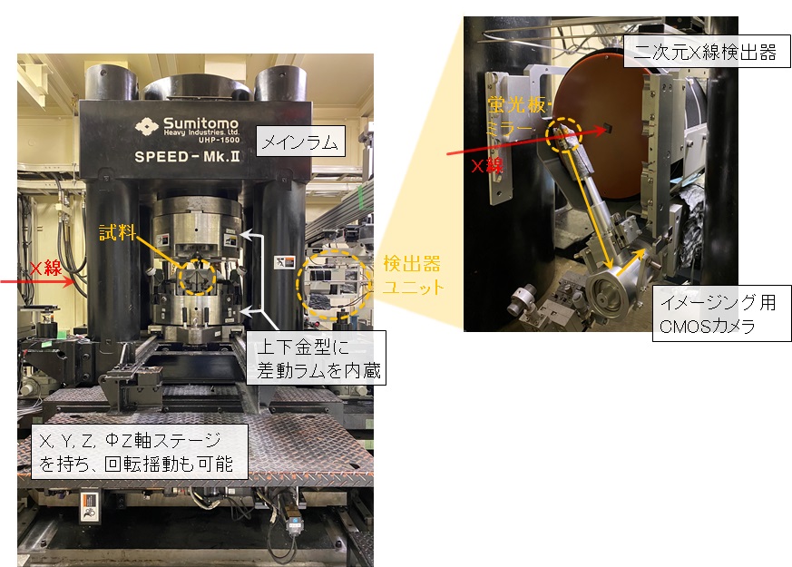
本システムは、比較的大型の試料(~mm3)を多軸圧縮で準静水圧環境下に晒すことができます。また、高圧セル内部の抵抗ヒーターで安定的に加熱できることから、高圧新奇物質のその場合成に適しています。本装置では高圧高温状態の試料に白色X線をそのまま照射して、X線吸収像の観察やエネルギー分散型XRD測定をおこなえ、更に高エネルギー単色X線を利用した角度分散型XRD計測も可能です。高圧プレス
本装置は2段押しの川井型高圧発生装置であり、最大1500トンの荷重を試料に加えることができます。本装置はメインラムに加えて、最大300トンの変形用ラムが内蔵されており、メインラムによる準静水圧加圧の後に、変形ラムによる1軸圧縮変形が可能です。また、本装置はアンビル面間距離の精度が高く焼結ダイヤモンドアンビルを使用して最大100GPa程度の高圧発生が可能です。高圧セル内部に抵抗加熱式ヒーターを組み込むことで3000℃までの加熱が可能です。
X線ビームモニター
X線吸収像の観察には浜松ホトニクス製のX線ビームモニターを使用しています。GAGG蛍光板で可視光に変換し、汎用のカメラ用光学レンズで結像します。カメラは同じく浜松ホトニクス製の科学計測用のsCMOSカメラを使用しています。見かけの分解能は約3μm/pixとなります。
Ge-SSD
XRD計測にはエネルギー分散型のX線回折法を採用してします。回折X線のエネルギースペクトル測定にはミリオンテクノロジーズ・キャンベラ社製のGe-SSDを常設しており、測定可能なエネルギー範囲は10~150keVです。
大面積2次元検出器
高エネルギー単色X線(エネルギー ~61keV)を利用した角度分散型X線回折測定ではRayonix社製の大面積CCD検出器を使用して、デバイリングを全周取得できます。特に、高圧変形実験で試料に加わる歪や応力測定に威力を発揮します。
◆装置アクセサリー
上記の高圧プレスで加熱するための、交流電源(2kW)と直流電源(1.5kW×3)を備えており、小型ヒーターに大電流(~300A)を印可して試料を数千度まで加熱できます。これらのX線計測機器の他に、試料の弾性波速度(弾性率)を測定するための超音波エコー測定システムや、4端子法で電気抵抗測定が可能なデジタルマルチメーターを利用できます。
◆実験・試料準備
基本的に一段目アンビルには一辺50mmと27mmの超硬合金製アンビルを使用し、二段目アンビルには一辺26mmと14mmの超硬製アンビルまたは、焼結ダイヤモンド製アンビルを使用できる他に、6-6加圧用ガイドフレームが利用でき、手軽に一段加圧用の立方形の圧力媒体が使用できます。角度分散型X線回折実験にはコーン型の切り込み付きの一段目アンビルを使用して、2θ=10°までの回折角のデータが取得できるが、デバイリングを全周取得するためには、コーン型の切り込み付きの二段目アンビル、またはX線の透過性に優れたc-BN製アンビル等を特別に用意しなければなりません。
◆実験手順・注意事項
実験手順の詳細はBL担当者にお聞きください。
一般的な実験手順として、
(1)高圧セル、試料準備
希望する圧力・温度・酸素雰囲気等により高圧セルを設計、パーツを製作する。試料は粉体のペレットもしくは焼結体を用意する。
(2)装置校正
Ge-SSDのエネルギー校正、水平ゴニオメーターの2θ補正をおこなう。
(3)高圧セル設置&常圧測定
加圧前の試料の状態をX線ラジオグラフィーで確認し、XRDデータを取得する。常圧データはその後の高圧データを定量的に議論する際に非常に重要であり、圧力の計算にも欠かせない。
(4)加圧&圧力測定
大型プレスで高圧セルを加圧する。通常3~5ton/minでゆっくり加圧する。加圧中に高圧セル内の圧力標準物質のXRD測定によって得られる結晶格子の縮みから発生圧力を計算し、目標圧力に達するまで、加圧&圧力測定を繰り返す。通常数時間はかかる。
(5)加熱&データ測定
目標圧力に達した後に、内部ヒーターによる加熱を開始する。加圧によるヒーター変形があるため、ヒーターの安定性に注視しつつ、目標温度まで加熱する。昇温しつつ試料のXRDデータを取得して、相変化や格子定数変化をその場観察する。圧力―温度平面上で多数のデータを取得する場合は(4)~(5)を繰り返す。
チェ―ブロックによる高圧セルの設置の際や、大型プレスの操作時は重大事故につながる恐れがあるため、特に注意が必要です。
また、白色X線は照射物を著しく損傷させます。X線の軸上に不用意にケーブルや検出器等を設置しないようにお願いします。
◆問い合わせ先
肥後祐司 このメールアドレスはスパムボットから保護されています。閲覧するにはJavaScriptを有効にする必要があります。
丹下慶範 このメールアドレスはスパムボットから保護されています。閲覧するにはJavaScriptを有効にする必要があります。
◆代表的な論文リスト
Sharp 660-km discontinuity controlled by extremely narrow binary post-spinel transition
Takayuki Ishii, Rong Huang, Robert Myhill, Hongzhan Fei, Iuliia Koemets, Zhaodong Liu, Fumiya Maeda, Liang Yuan, Lin Wang, Dmitry Druzhbin, Takafumi Yamamoto, Shrikant Bhat, Robert Farla, Takaaki Kawazoe, Noriyoshi Tsujino, Eleonora Kulik, Yuji Higo, Yoshinori Tange & Tomoo Katsura
Nature Geoscience 23 Sep. 2019:
Vol. 12, pp. 869-872
DOI: 10.1038/s41561-019-0452-1
Intermediate-depth earthquakes linked to localized heating in dunite and harzburgite
Tomohiro Ohuchi, Xinglin Lei, Hiroaki Ohfuji, Yuji Higo, Yoshinori Tange, Takeshi Sakai, Kiyoshi Fujino & Tetsuo Irifune
Nature Geoscience 28 Aug. 2017:
Vol. 10, pp. 771-776
DOI: 10.1038/ngeo3011
Mantle dynamics inferred from the crystallographic preferred orientation of bridgmanite
Noriyoshi Tsujino, Yu Nishihara, Daisuke Yamazaki, Yusuke Seto, Yuji Higo & Eiichi Takahashi
Nature 17 Mar 2016:
Vol. 539, pp. 81-84
DOI: 10.1038/nature19777
Stability of hydrous silicate at high pressures and water transport to the deep lower mantle
M. Nishi, T. Irifune, J. Tsuchiya, Y. Tange, Y. Nishihara, K. Fujino & Y. Higo
Nature Geoscience 02 Feb. 2014:
Vol. 7, pp. 224-227
DOI: 10.1038/ngeo2074
P-V-T equation of state for ε-iron up to 80 GPa and 1900 K using the Kawai-type high pressure apparatus equipped with sintered diamond anvils
Daisuke Yamazaki, Eiji Ito, Takashi Yoshino, Akira Yoneda, Xinzhuan Guo, Baohua Zhang, Wei Sun, Akira Shimojuku, Noriyoshi Tsujino, Takehiro Kunimoto, Yuji Higo, Ken Ichi Funakoshi
Geophysical Research Letters 28 Oct. 2012
Vol. 39, no. 20. pp. 20308-
DOI: 10.1029/2012GL053540
Large Capacity, High-Pressure Generating Equipment with Transformation Mechanisms (SPEED-Mk II)
◆Equipment overview
Large capacity samples(~mm3)can be pressurized and heated up to 100GPa. In addition to the main ram, a sub-ram is provided for transformation in the guide block, allowing transformation experiments under high pressure.

◆Features of the Equipment
This system can expose relatively large-sized samples(~mm3)to multi-axis compression in a quasi-hydrostatic environment. Also, since it can be heated stably with a resistance heater inside a high-pressure cell, it is suited for cases of high-pressure substances. With this equipment, samples in high-temperature, high-pressure states can be irradiated with white X-rays, to observe X-ray absorption images, perform energy distribution XRD measurements, and even angle distribution XRD measurements using high-energy monochromatic X-rays.High-Pressure Press
This equipment is a 2-stage, Kawai-type high pressure generator that can apply loads up to 1,500 tons per sample. In addition to the main ram, there is a built-in transformation ram that is capable of applying a load of 300 tons, and after the main ram pressurizes to quasi-hydrostatic pressure, single axis compression transformation is possible by the transformation ram. Also, this equipment has a high precision distance between the anvil surfaces, and high pressures of up to 100GPa can be generated using a sintered diamond anvil. By incorporating a resistance heater inside the high-pressure cell, it is possible to heat to 3000℃.
X-ray Beam Monitor
X-ray absorption images are observed using an X-ray beam monitor manufactured by Hanamatsu Photonics. It is converted to visible light using a GAGG fluorescent plate, then imaged with a general-purpose optical camera lens. The camera used for scientific measurements is a sCMOS camera, also manufactured by Hanamatsu Photonics. The effective resolution is approximately 3μm/pix.
Ge-SSD
XRD measurement uses energy-dispersive X-ray diffraction. Measurements of the X-ray diffraction energy spectrum are completed using a permanently installed Ge-SSD manufactured by Mirion Technologies (Canberra), with a measurable energy range of 10~150keV.
Large Area 2-Dimensional Detector
For angular transformation X-ray diffraction measurements using high-energy, monochromatic X-rays (energy ~61keV), the Debye-Scherrer ring can be obtained using a large-area CCD detector manufactured by Rayonix. In particular, it is effective for strain and stress measurements applied to high-pressure transformation experiments.
◆Equipment accessories
For heating with the above high-pressure press, an AC power supply of (2kW) and a DC power supply of(1.5kW×3)is equipped, a large current(~300A)can be applied to a small heater to heat the sample to several thousand degrees.
In addition to these X-ray measurement instruments, there is an ultrasound echo measurement system used to measure the elastic wave velocity (modulus of elasticity) of the sample, as well as a four-terminal digital multimeter to measure electric resistance.
◆Experiment / sample preparation
For the first stage, a 50mm by 27mm carbide anvil is used, and for the second stage a 26mm by 14mm carbide anvil is used. In addition, a sintered diamond anvil can also be used, as well as a 6-6 guide frame for pressurization, making it easy to use standard pressure mediums for pressurizations. For angle dispersion X-ray diffraction experiments, a cone-shaped, first-stage anvil is used allowing for 2θ=10°diffraction data to be acquired. In order to obtain the entire rotation of the Debye-Scherrer ring, a cone-shaped anvil is used at the second-stage, also a c-BN anvil which has excellent X-ray transparency must be specially prepared.
◆Experimental procedure / precautions
For details on experimental procedures, please ask the person in charge of the BL.
General experimental procedure,
(1)High Pressure Cell, Sample Preparation
High-pressure cells are designed and created depending on the desired pressure, temperature, oxygen atmosphere, etc. The sample is prepared using powdered pellets or sintered bodies.
(2)Instrument Calibration
Ge-SSD energy calibrations and 2θ goniometer calibrations are performed.
(3)High-Pressure Cell Installation and Standard Pressure Measurements
The state of the sample before pressurization is confirmed by X-ray radiography, then XRD data can be acquired. The constant pressure data is significant for quantitative discussions of high-pressure data, and is essential for computing pressure.
(4)Increasing Pressure & Pressure Measurements
The high-pressure cell can be pressurized with the large press. It usually takes 3~5ton/min to slowly pressurize. During pressurization, the generated pressure is calculated from the shrinking of the crystal lattice structure, obtained by XRD measurements of the high-pressure cell inside the substance. The pressurization and pressure measurements are repeated until the target pressure is reached, which usually takes several hours.
(5)Heating & Data Measurements
After reaching the target pressure, heating is started with an internal heater. Since there is a heater transformation due to pressurization, it must be heated to the target temperature while the stability of the heater is carefully observed. The XRD data of the sample is acquired while the temperature rises, and phase changes as well as lattice changes are observed.
Repeat (4) ~ (5) when a large amount of data is acquired on the pressure – temperature plane.
Special care must be paid to the installation of high-pressure cells with chain blocks, as well as when operating large presses, as this may lead to serious accidents.
Also, white X-rays significantly damage whatever they irradiate. Please no not install cables, detectors, etx on the X-ray axis.
◆Contact
肥後祐司 このメールアドレスはスパムボットから保護されています。閲覧するにはJavaScriptを有効にする必要があります。
丹下慶範 このメールアドレスはスパムボットから保護されています。閲覧するにはJavaScriptを有効にする必要があります。
◆List of representative treatises
Sharp 660-km discontinuity controlled by extremely narrow binary post-spinel transition
Takayuki Ishii, Rong Huang, Robert Myhill, Hongzhan Fei, Iuliia Koemets, Zhaodong Liu, Fumiya Maeda, Liang Yuan, Lin Wang, Dmitry Druzhbin, Takafumi Yamamoto, Shrikant Bhat, Robert Farla, Takaaki Kawazoe, Noriyoshi Tsujino, Eleonora Kulik, Yuji Higo, Yoshinori Tange & Tomoo Katsura
Nature Geoscience 23 Sep. 2019:
Vol. 12, pp. 869-872
DOI: 10.1038/s41561-019-0452-1
Intermediate-depth earthquakes linked to localized heating in dunite and harzburgite
Tomohiro Ohuchi, Xinglin Lei, Hiroaki Ohfuji, Yuji Higo, Yoshinori Tange, Takeshi Sakai, Kiyoshi Fujino & Tetsuo Irifune
Nature Geoscience 28 Aug. 2017:
Vol. 10, pp. 771-776
DOI: 10.1038/ngeo3011
Mantle dynamics inferred from the crystallographic preferred orientation of bridgmanite
Noriyoshi Tsujino, Yu Nishihara, Daisuke Yamazaki, Yusuke Seto, Yuji Higo & Eiichi Takahashi
Nature 17 Mar 2016:
Vol. 539, pp. 81-84
DOI: 10.1038/nature19777
Stability of hydrous silicate at high pressures and water transport to the deep lower mantle
M. Nishi, T. Irifune, J. Tsuchiya, Y. Tange, Y. Nishihara, K. Fujino & Y. Higo
Nature Geoscience 02 Feb. 2014:
Vol. 7, pp. 224-227
DOI: 10.1038/ngeo2074
P-V-T equation of state for ε-iron up to 80 GPa and 1900 K using the Kawai-type high pressure apparatus equipped with sintered diamond anvils
Daisuke Yamazaki, Eiji Ito, Takashi Yoshino, Akira Yoneda, Xinzhuan Guo, Baohua Zhang, Wei Sun, Akira Shimojuku, Noriyoshi Tsujino, Takehiro Kunimoto, Yuji Higo, Ken Ichi Funakoshi
Geophysical Research Letters 28 Oct. 2012
Vol. 39, no. 20. pp. 20308-
DOI: 10.1029/2012GL053540
