ピンポイント構造計測装置
◆装置概要
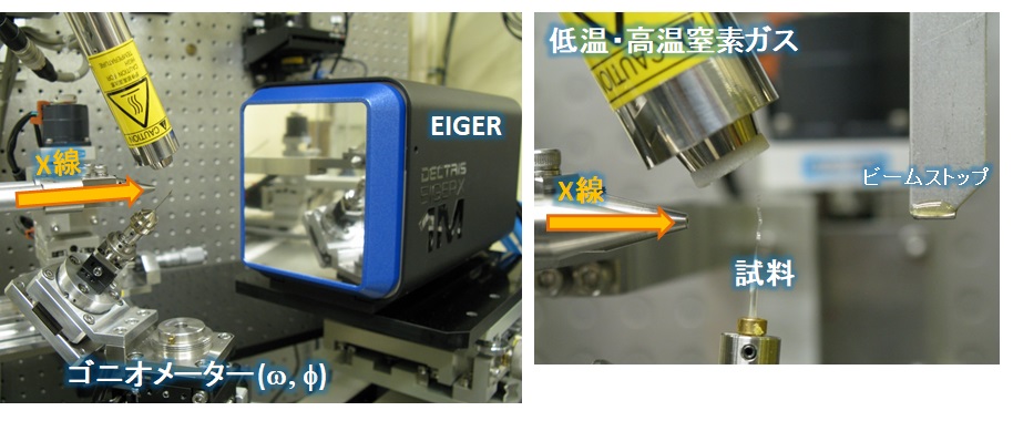
本装置はヘリカルアンジュレータから発生した高フラックスビームやゾーンプレートによる集光ビームを利用した「微小単結晶構造解析」や「結晶性試料の回折像マッピング」を行うための精密回折計です。

◆装置の特徴
回折計、検出器、制御ソフトなどについて記載。装置の選定に必要なビーム強度、ビームサイズ、X線エネルギーの情報も記載。本装置は高フラックスビームやゾーンプレートを利用した集光ビームを利用して微小単結晶構造解析や結晶性試料の回折像をマッピング測定することが可能です。
利用できるX線
ヘリカルアンジュレータから発生したエネルギー幅の広いピンクビームと実験ハッチ内のSi(111)チャンネルカットモノクロメータで単色化した単色ビームが利用できます。
| ピンクビーム | E=8~16keV、ΔE/E~2% |
| 単色ビーム | E=8~16keV、ΔE/E~0.02% |
集光ビーム
光学ハッチ内の縦横集光ミラーによる数10~数100μmサイズのミラー集光ビーム、およびゾーンプレート集光によるマイクロ~サブマイクロビームが利用可能です。また、スリット整形による平行ビームも利用できます。
ミラー集光ビーム(E=8~16keV)
光学ハッチ内の縦横集光ミラーによって試料位置に集光します。
| ピンクビーム(E=12.2keV、FE Slit 0.165×0.3mm) | |
| ビームサイズ | 40 × 300 μm |
| ビーム強度 | 2.6 × 10¹³ photons/sec |
| 単色X線(E=15keV、FE Slit 0.165×0.3mm) | |
| ビームサイズ | 30 × 250 μm |
| ビーム強度 | 1.4 × 10¹² photons/sec |
ゾーンプレート集光(通常8keVまたは15keVで利用、単色X線のみ)
ミラー集光によってハッチ1上流に仮想光源を置き、回折計上に設置したゾーンプレートによって試料位置に集光します。集光サイズによって2タイプのゾーンプレートが利用できます。
| ゾーンプレートType1(マイクロビーム用、15.4keV利用) | ||
| ビームサイズ | 1 × 3 μm | FE Slit 0.165×0.3mm 仮想光源Slitなし |
| ビーム強度 | 1 × 10¹⁰ photons/sec | − |
| ゾーンプレートType2(サブミクロンビーム用、8keV利用) | ||
| ビームサイズ | 300 × 300 nm | FE Slit 0.165×0.3mm 仮想光源Slit 50 × 50μm |
| ビーム強度 | 1 × 10⁸ photons/sec | − |
| ビームサイズ | 640 × 800 nm | FE Slit 0.165×0.3mm 仮想光源Slitなし |
| ビーム強度 | 1 × 10⁹ photons/sec | − |
平行ビーム
ハッチ1にミラー集光した後のビームをスリット整形します。通常はモノクロメータで単色化したX線を利用します。
| ビームサイズ | 5~200 μm | E=15keV単色X線 FE Slit 0.165 × 0.3 mm 150 × 150 μmスリット |
| ビーム強度 | 4 × 10¹⁰ photons/sec | − |
検出器
本回折計は通常半導体検出器(DECTRIS EIGER X 1M)または湾曲イメージングプレートを排他的に利用することができます。また、持込みの検出器を2θステージなどに取り付けて測定を行うことも可能です。
半導体検出器(DECTRIS EIGER X 1M)
本検出器は、シリコン素子を利用した半導体検出器であり、ピクセルサイズ75×75 μm、画素数1030×1065ピクセルで最大3000 Hzのフレームレート(読み取り時間3 μs)で測定を行えます。高速読み出しの利点を生かして単結晶の回折測定ではシャッターレス測定が可能です。カメラ長は55~300 mmの範囲で変更できます。
湾曲イメージングプレート(IP)
IP(サイズ20×40 cm)を利用するための湾曲IPステージも取り付けが可能です。カメラ長は286.5 mm固定で2θ<80°の粉末X線回折測定などに利用できます。読み取りは実験ハッチ外にあるIPリーダーに読み込ませる必要があります。
ゴニオメータ
試料回転のためにω、χ、φ軸の3軸を有しており、通常ω軸は0~180°、φ軸は0~360°、χ軸は0°または45°で利用できます。2θステージは2θ<120°程度の移動が可能であり、カメラ長も300 mm程度まで任意に変更可能です。また、試料移動用のモータ駆動XYZステージでは5 nmステップでのマッピング測定ができ、精度が必要な場合には1 nm分解能のピエゾステージも利用できます。
制御ソフトウェア
回折計や検出器はNational Instruments製Labviewをベースとしたプログラムで制御されており、事前の打ち合わせによって持込み装置の制御や実験に必要なルーチンを組み込むことが可能です。
◆装置アクセサリー
本システムでは、下記のアクセサリーの使用が可能です。
・窒素吹付型低温装置(90~400K)
・窒素吹付型高温装置(室温~1000K)
・X線パルスセレクター(1kHzまたは2kHz)
・フェムト秒レーザー(チタンサファイアレーザー、波長800nm)
◆実験・試料準備
測定の際に試料を取り付けるホルダは実験室系の装置で一般的に使用されるマイクロマウントやループ、またはガラス針を利用できる(ベースからの高さ20mm程度)。ゴニオメータヘッドにはマグネットやφ3mmの金属棒部分で保持することが可能です。空気中で溶媒脱離などにより結晶性が劣化する場合にはビームラインに設置された実体顕微鏡を利用してビームラインでの試料取り付けも可能です。
◆実験手順・注意事項
【単結晶構造解析実験の一般的な流れ】
1)試料を試料ホルダに取り付ける
試料ホルダは一般的に実験室系で利用されるマイクロマウント、ループ、ガラス針が利用できる。(ベースからの高さ20mm程度)
2)試料ホルダを回折計に取り付ける
3)センタリング
φ、ω軸に対してセンタリングを行います。
4)結晶性のチェック
短時間(<1分)の測定を行って結晶性や回折強度をチェックします。
5)データ測定
チェック測定の結果を基にして露光時間やX線強度を決定してデータ測定を行う。
通常はφ:0,90,180,270°の各位置でω:0~180°の範囲をΔω1°毎に回折像を取得する。EIGERの読み取り時間が短いため、シャッターレス測定が行われ、1秒露光の場合約12分で全反射の測定が完了する。
6)回折強度の積分
ビームラインに導入されている積分用ソフトウェアを利用して回折像から回折強度を抽出する。
利用可能なソフト:Rapid Auto, CrysAlis(Pro) (RIGAKU) APEX3(Bruker)
7)構造解析
積分処理によって得られた結晶学データおよび回折強度データから構造解析を行う。実験後に大学などで解析を進める場合も多く、実験者の使い慣れたソフトでの解析を行うため、原則として構造解析用のソフトウェアはユーザーが準備することを推奨している。ビームラインではCrystalStructure(RIGAKU)が利用可能です。
◆問い合わせ先
安田 伸広(このメールアドレスはスパムボットから保護されています。閲覧するにはJavaScriptを有効にする必要があります。)
◆代表的な論文リスト
Arylethynyl Groups That Modulate Anion-Binding and Assembling Modes of Rod- and Fan-Shaped π-Electronic Systems
Watanabe, Y.; Haketa, Y.; Nakamura, K.; Kaname, S.; Yasuda, N.; Maeda, H.
Chem. Eur. J., 2020, 26, 6767-6772.
DOI: https://doi.org/10.1002/chem.202000634
Manipulation of the Coordination Geometry along the C4 Rotation Axis in a Dinuclear Tb3+ Triple‐Decker Complex via a Supramolecular Approach
Keiichi Katoh, Nobuhiro Yasuda, Marko Damjanović, Wolfgang Wernsdorfer, Brian K. Breedlove, Masahiro Yamashita
Chem. Eur. J., 2020, 26, 4805-4815.
DOI: https://doi.org/10.1002/chem.201905400
Thermal Behavior, Crystal Structure, and Solid-State Transformation of Orthorhombic Mo-V Oxide under Nitrogen Flow or in Air
M. Sadakane, K. Kodato, N. Yasuda, S. Ishikawa, W. Ueda
Acs Omega, 2019, 4(8), 13165-13171.
DOI: https://doi.org/10.1021/acsomega.9b01212
Object Transportation System Mimicking the Cilia of Paramecium aurelia Making Use of the Light-Controllable Crystal Bending Behavior of a Photochromic Diarylethene
R. Nishimura, A. Fujimoto, N. Yasuda, M. Morimoto, T. Nagasaka, H. Sotome, S. Ito, H. Miyasaka, S. Yokojima, S. Nakamura, B. L. Feringa, K. Uchida
Angew. Chem. Int. Ed., 2019, 58(38), 13308-13312.
DOI: https://doi.org/10.1002/anie.201907574
Mechanically interlocked architecture aids an ultra-stiff and ultra-hard elastically bendable cocrystal
Somnath Dey, Susobhan Das, Surojit Bhunia, Rituparno Chowdhury, Amit Mondal, Biswajit Bhattacharya, Ramesh Devarapalli, Nobuhiro Yasuda, Taro Moriwaki, Kapil Mandal, Goutam Dev Mukherjee & C. Malla Reddy
Nat Commun, 10, 3711 (2019).
DOI: https://doi.org/10.1038/s41467-019-11657-0
Synthesis of Tetracoordinate Boron‐Fused Benzoaceanthrylene Analogs via Tandem Electrophilic C−H Borylation
Susumu Oda, Hiroaki Abe, Nobuhiro Yasuda, Takuji Hatakeyama
Chem. Asian J., 14, 1657-1661 (2019).
DOI: https://doi.org/10.1002/asia.201801682
Pinpoint Structure Measurement Equipment
◆Equipment overview
This equipment includes a precision diffractometer which uses high-flux beams generated by helical undulators and focusing beams using zone plates in order to achieve micro single crystal structure analysis and diffraction mapping of crystal samples.

◆Features of the Equipment
Diffractometers, detectors, control software and more are listed. Information on equipment selection including beam intensity, beam size and X-ray energy are also described.This equipment includes a high-flux beam and a focusing beam which uses zone plates, which can perform micro single crystal structure analysis as well as measurements and mapping of diffraction images of crystal structures.
Available X-rays
A wide-energy, monochromatic pink beam is available, which is generated from a helical undulator and an Si (111) channel-cut monochromator in the experimental hatch.
| Pink beam | E=8~16keV、ΔE/E~2% |
| Monochromatic beam | E=8~16keV、ΔE/E~0.02% |
Focusing Beam
Inside the optical hatch are length and width concentration mirrors which focus the beams to 10 ~ 100 μm in size, as well as a zone plate which focuses micro to submicro beams. Also, parallel beams which were shaped by slits are also available.
Focusing Beam Mirror (E=8~16keV)
The length and width mirror inside the optical hatch collects the light at the sample position.
| Pink Beam (E=12.2keV、FE Slit 0.165×0.3mm) | |
| Beam Size | 40 × 300 μm |
| Beam Intensity | 2.6 × 10¹³ photons/sec |
| Monochromatic X-ray (E=15keV、FE Slit 0.165×0.3mm) | |
| Beam Size | 30 × 250 μm |
| Beam Intensity | 1.4 × 10¹² photons/sec |
Zone plate focusing (Usually used at 8keV or 15keV, monochromatic X-rays only)
A virtual light source is placed upstream of hatch 1 due to a focusing mirror, and the sample position is focused by the zone plate installed at the diffractometer.
| Zone Plate Type1 (for microbeams, using 15.4keV) | ||
| Beam Size | 1 × 3 μm | FE Slit 0.165 × 0.3mm No virtual light source slit |
| Beam Intensity | 1 × 10¹⁰ photons/sec | - |
| Zone Plate Type2(for submicron beams, using 8keV) | ||
| Beam Size | 300 × 300 nm | FE Slit 0.165 × 0.3mm Virtual light source slit 50 × 50μm |
| Beam Intensity | 1 × 10⁸ photons/sec | - |
| Beam Size | 640 × 800 nm | FE Slit 0.165×0.3mm No virtual light source slit |
| Beam Intensity | 1 × 10⁹ photons/sec | - |
Parallel Beam
The mirror in the 1st hatch focuses the beam after it is shaped by the slit. Generally, a monochromator is used to achieve monochromatic X-rays.
| Beam Size | 5~200 μm | E=15keV Monochromatic X-rays FE Slit 0.165 × 0.3 mm 150 × 150 μm slit |
| Beam Intensity | 4 × 10¹⁰ photons/sec | - |
Detector
This diffractometer is exclusively used for semiconductor detectors (DECTRIS EIGER X 1M) or curved imaging plates. Also, it is possible to measure by attaching a bring-in detector to a 2θ stage or the like.
Semiconductor Detector (DECTRIS EIGER X 1M)
This detector is a semiconductor detector using the element silicon, with a pixel size of 75×75 μm, number of pixels 1030×1065 pixels, with a maximum frame rate of 3000 Hz (read time 3 μs). With shutterless measurements, the advantage is high-speed read-outs, allowing for diffraction measurements of single crystals. The camera length has a changeable length between 55~300 mm.
Curved Imaging Plate (IP)
An IP (size 20×40 cm) can be installed on the curved IP stage. The camera length is fixed at 286.5 mm and can be used for powder X-ray diffraction measurements for 2θ<80°. Results are read by the IP reader outside the experimental hatch.
Goniometer
For sample rotation, it has three axes, ω,χ,φ, and generally ω ranges from 0~180°, φ ranges from 0~360°, and χ 0° or 45°. The 2θ has a range of movement of 2θ<120°, and the camera length can be changed to a maximum of 300 mm. The motor-driven XYZ for sample movement can be mapped in 5nm steps, and a piezo stage of 1nm resolution is available when accuracy is required.
Control Software
Diffractometer and detectors are controlled by a program based on National Instruments Labview, allowing for incorporation of routines necessary for control and experimentation for bring-in equipment before the meeting.
◆Equipment accessories
The following accessories can be used with this system.
・Low-temperature Nitrogen spray equipment (90~400K)
・High-temperature Nitrogen spray equipment (Room temperature~1000K)
・X-ray Pulse Selector (1kHz or 2kHz)
・Femtosecond laser (Titanium sapphire laser, 800nm wavelength)
◆Experiment / sample preparation
While taking measurements, laboratory equipment sample holders are available, including micromounts, loops or glass needles (with the height from the base about 20mm). The goniometer head can be held with a magnet or a φ3mm metal rod. When crystallinity deteriorates due to solvent desorption in air, it is possible to mount the sample at the beamline using a stereo microscope installed on the beamline.
◆Experimental procedure / precautions
【General course single crystal structure analysis experiment】
1)Install the sample in the sample holder
Commonly used laboratory equipment sample holders are available, including micromounts, loops and glass needles (with the height from the base about 20mm).
2)Attach the sample holder to the diffractometer
3)Centering
φ,ω axes require centering.
4)Crystalline check
Complete a short measurement check (<1 minute) of crystallinity and diffraction intensity.
5)Data Measurement
Based on the results of the check measurement, the exposure time and the X-ray intensity are determined and the data measurement is performed.
Generally, diffraction images are obtained every Δω1°in the range of ω:0~180°for each of the positions φ:0,90,180,270°. The EIGER read time is short due to shutterless measurements, and 1 second exposure allows for the total reflection measurements to be completed in approximately 12 minutes.
6)Integrate Diffraction Intensity
Diffraction intensity is extracted from the diffraction image using the integral software introduced in the beamline.
Available software: Rapid Auto, CrysAlis(Pro) (RIGAKU) APEX3(Bruker)
7)Structure Analysis
Structure analysis is performed from crystallography data and diffraction intensity data through the use of integral processing. It is recommended that users prepare software for structural analysis in order to perform analysis with software familiar to the experimenters, as analysis is often carried out at universities and other facilities after the experiment. CrystalStructure(RIGAKU) is available on the beamline.
◆Contact
安田 伸広(このメールアドレスはスパムボットから保護されています。閲覧するにはJavaScriptを有効にする必要があります。)
◆List of representative treatises
Arylethynyl Groups That Modulate Anion-Binding and Assembling Modes of Rod- and Fan-Shaped π-Electronic Systems
Watanabe, Y.; Haketa, Y.; Nakamura, K.; Kaname, S.; Yasuda, N.; Maeda, H.
Chem. Eur. J., 2020, 26, 6767-6772.
DOI: https://doi.org/10.1002/chem.202000634
Manipulation of the Coordination Geometry along the C4 Rotation Axis in a Dinuclear Tb3+ Triple‐Decker Complex via a Supramolecular Approach
Keiichi Katoh, Nobuhiro Yasuda, Marko Damjanovi?, Wolfgang Wernsdorfer, Brian K. Breedlove, Masahiro Yamashita
Chem. Eur. J., 2020, 26, 4805-4815.
DOI: https://doi.org/10.1002/chem.201905400
Thermal Behavior, Crystal Structure, and Solid-State Transformation of Orthorhombic Mo-V Oxide under Nitrogen Flow or in Air
M. Sadakane, K. Kodato, N. Yasuda, S. Ishikawa, W. Ueda
Acs Omega, 2019, 4(8), 13165-13171.
DOI: https://doi.org/10.1021/acsomega.9b01212
Object Transportation System Mimicking the Cilia of Paramecium aurelia Making Use of the Light-Controllable Crystal Bending Behavior of a Photochromic Diarylethene
R. Nishimura, A. Fujimoto, N. Yasuda, M. Morimoto, T. Nagasaka, H. Sotome, S. Ito, H. Miyasaka, S. Yokojima, S. Nakamura, B. L. Feringa, K. Uchida
Angew. Chem. Int. Ed., 2019, 58(38), 13308-13312.
DOI: https://doi.org/10.1002/anie.201907574
Mechanically interlocked architecture aids an ultra-stiff and ultra-hard elastically bendable cocrystal
Somnath Dey, Susobhan Das, Surojit Bhunia, Rituparno Chowdhury, Amit Mondal, Biswajit Bhattacharya, Ramesh Devarapalli, Nobuhiro Yasuda, Taro Moriwaki, Kapil Mandal, Goutam Dev Mukherjee & C. Malla Reddy
Nat Commun, 10, 3711 (2019).
DOI: https://doi.org/10.1038/s41467-019-11657-0
Synthesis of Tetracoordinate Boron‐Fused Benzoaceanthrylene Analogs via Tandem Electrophilic C?H Borylation
Susumu Oda, Hiroaki Abe, Nobuhiro Yasuda, Takuji Hatakeyama
Chem. Asian J., 14, 1657-1661 (2019).
DOI: https://doi.org/10.1002/asia.201801682
