100Jレーザー(超高圧科学)
XFELと100J級のハイパワーナノ秒レーザーを組み合わせることで、ハイパワーレーザーによって作り出せる超高圧力状態にある物質を超高速に診断することができます。本ページでは、BL3 EH5におけるハイパワーナノ秒レーザー利用実験について紹介します。
※ハイパワーナノ秒レーザー装置は、大阪大学が中心となって整備されました。
※この実験システムは、ハイパワーナノ秒レーザーのユーザーグループと共同で開発整備されました。一部のシステムの高度化は、SACLA基盤開発プログラムの課題(代表者:大阪大学 尾崎典雅准教授)として実施されています。
参考文献:
Y. Inubushi et. al., Appl. Sci. 10, 2224 (2020).
基本性能・成果
衝撃圧縮されたコランダムのX線回折計測
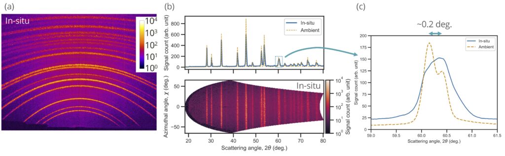
計測例として多結晶コランダムのX線回折データを示します。ハイパワーナノ秒レーザー照射によって圧縮されている様子が観測できています。
試料チャンバ内に設置できるフラットパネルディテクタを用いることによって広い角度範囲(回折角: 18–78°、方位角:+/-60°)での計測が可能です。
多結晶コランダムからのX線回折
レーサー集光条件および生成圧力
典型的なレーザー集光スポットサイズは200–300 µm程度、照射強度は~1 × 10¹³ W/cm2程度までであり、固体試料の場合、数100 GPaの圧力の生成が可能です。
実験装置
試料チャンバ
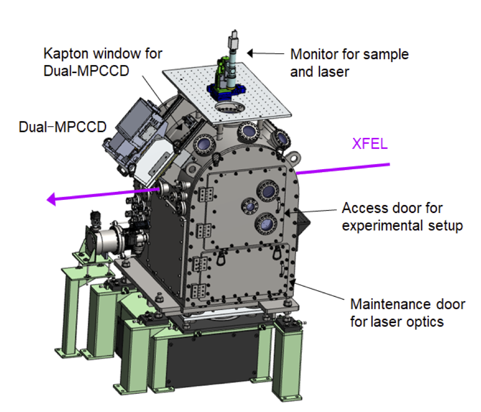
ハイパワーナノ秒レーザー実験には、SACLA BL3の最下流、実験ハッチEH5内に常設されている真空試料チャンバを使用します。この試料チャンバ内に設置した試料にXFELとハイパワーナノ秒レーザーを照射して実験を行います。
試料チャンバ

試料チャンバ内部
試料駆動機構および試料ホルダ
試料チャンバ内に、試料をアライメントするための多軸ステージが常設されています。
標準の試料ホルダシステムは試料を固定する短冊状(100 mm × 10 mm)のサンプルプレートとそのサンプルプレートを固定するフレームから構成されています。フレームは磁石式のキネマティックベースによって駆動機構と接続されます。試料ホルダシステムは実験に合わせて変更することができます。
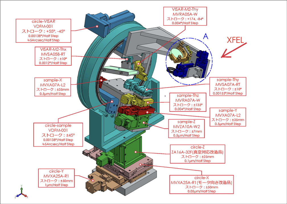
試料チャンバ内駆動機構
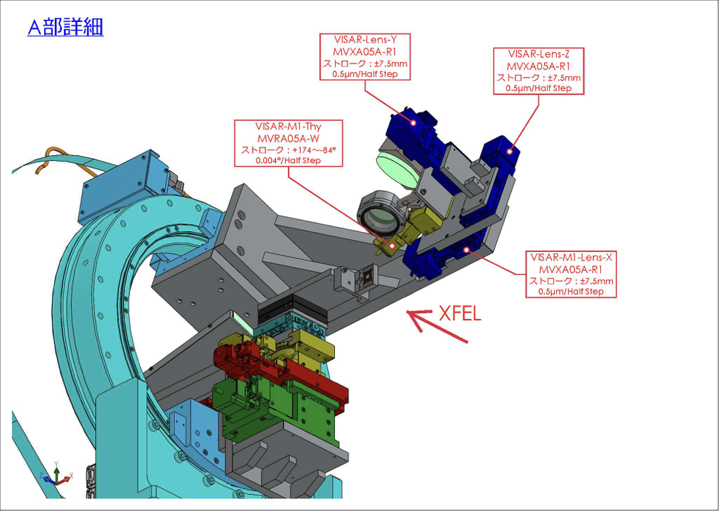
試料チャンバ内駆動機構A部詳細
運転パラメータ(EH5@BL3)
XFELパラメータ
| 光子エネルギー(基本波) | 4-20 keV |
| パルスエネルギー | 光子エネルギーに依存(下図参照) |
| エネルギー幅(ΔE/E) | ~0.5%(ニ結晶分光器なし) |
| 繰り返しレート | 30 Hz(BL2&3同時運転時) |
参考文献:
M. Yabashi et al., J. Synchrotron Rad. 22, 477 (2015).
K. Tono et al., J. Synchrotron Rad. 26, 595 (2019).
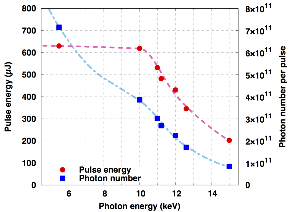
(参考)光子エネルギーとパルスエネルギー・光子数の関係(BL3の場合)
X線集光特性
X線回折の分解能を担保するために、縦方向の発散角は1 mrad以下となるよう設計された下記のKBミラー光学系を利用して、実験に合わせてXFELの集光サイズを調節することが可能です。また、片側のミラーのみを用いることで、X線を一次元に集光することも可能です。
非集光の場合の典型的なXFELビーム径は600 µm(半値全幅)であり、四象限スリットによって任意のサイズに調整可能です。
| Optical parameters (KB mirrors) | Vertical | Horizontal |
| Surface coating | Rhodium | Rhodium |
| Substrate size | 300 × 50 × 50 mm | 400 × 50 × 50 mm |
| Glancing angle | 4.0 mrad | 3.7 mrad |
| Focal length | 1200 mm | 800 mm |
| Distance from source | ~260 m | ~260 m |
| Spatial acceptance | > 1.2 mm | > 1.4 mm |
| Divergent angle | ~1 mrad | ~2 mrad |
| Typical focal size @10keV | ~430 nm FWHM | ~480 nm FWHM |
参考文献:
Y. Inubushi et. al., Appl. Sci. 10, 2224 (2020).
光学レーザー特性
| ハイパワーナノ秒レーザー | |
| Wavelength | 532 nm |
| Pulse Energy (Max.) | ~60 J(10 ns矩形波)* |
| Pulse Duration | 3-10 ns |
| Rep. Rate | 0.1 Hz |
*最大エネルギーはパルス波形に依存します。
標準的な実験配置
X線計測手法例と実験配置
X線回折
・XFELをプローブとした、ハイパワーナノ秒レーザーが照射された試料からの広角X線回折計測。
・検出器には試料チャンバ内に設置できるフラットパネルディテクタ(シンチレーションCMOSカメラ)またはチャンバ外に設置できるDual-MPCCDが使用可能。
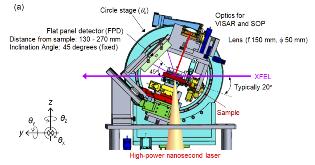
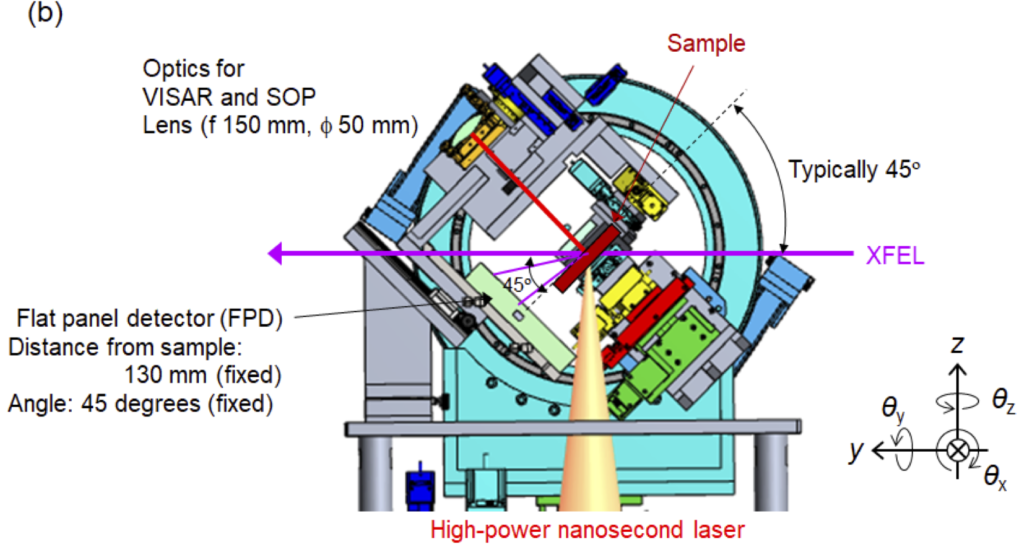
・フラットパネルディテクタを使用する場合、反射配置と透過配置での計測が可能。

X線回折反射配置

X線回折透過配置
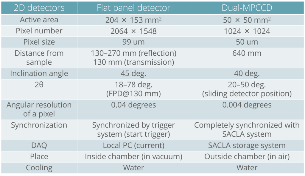
X線回折用検出器
小角X線散乱
- ・XFELをプローブとした、ハイパワーナノ秒レーザーが照射された試料からの小角X線散乱計測。
- ・試料チャンバ下流に検出器を設置。
X線イメージング
- ・XFELをプローブとした、ハイパワーナノ秒レーザーが照射された試料のイメージング計測。
- ・試料下流に検出器を設置。
光学計測手法例と実験配置
速度干渉計測(VISAR)
- ・光学レーザーをプローブとした、ハイパワーナノ秒レーザーが照射された試料の速度計測。
- ・回折計の回転ステージ(Circle stage, θx)に設置されている光学系を利用可能。
放射輝度温度計測(SOP)
- ・ハイパワーナノ秒レーザーが照射された試料からの自発光輝度温度計測。
- ・回折計の回転ステージ(Circle stage, θx)に設置されている光学系を利用可能。
測定までの調整作業
ビームタイムまでにSACLAのスタッフが行うこと
- ・ハイパワーナノ秒レーザーの試料チャンバへの導入
- ・施設装置のセットアップ、初期アライメント
- ・XFELスペクトル、光軸、集光調整
- ・XFELとハイパワーナノ秒レーザーのおおまかな空間合わせ
- ・XFELとハイパワーナノ秒レーザーの高速PDを用いた時間合わせ
ビームタイム開始後にユーザーが行うこと
- ・XFELとハイパワーナノ秒レーザーの精密空間合わせ
- ・常設装置の精密アライメント
- ・ユーザー持ち込み装置の精密アライメント
- ・XFELとハイパワーナノ秒レーザー、計測器の精密時間合わせ
- ・試料のアライメント
- ・XFEL、ハイパワーナノ秒レーザーの照射
- ・計測機器のオペレーション
測定手順
ビームタイム初期調整終了後は、典型的には以下の手順で実験を行います。
- 1.試料チャンバ内への試料の設置
- 2.試料チャンバ真空引き
- 3.ハイパワーナノ秒レーザーと試料の相互作用点決定
- 4.ハイパワーナノ秒レーザーのポインティング調整
- 5.計測機器の調整
- 6.試料アライメント
- 7.データ取得ショット
- 8.試料チャンバ大気解放
SACLA標準の検出器のデータは、SACLAのHPCを利用してアクセス可能です。
100J laser (Ultra High-Pressure Science)
By combining XFEL with a 100J-class high-power nanosecond laser, ultra-fast diagnostics of ultra-high-pressure materials created by high-power lasers is possible. This page introduces high-power nanosecond laser experiments at BL3 EH5.
※The high-power nanosecond laser equipment was mainly developed by Osaka University.
※ This experimental system was developed in collaboration with a user group for high-power nanosecond lasers. The sophistication of some systems is being upgraded by the SACLA Basic Development Program (representative: associate professor Norimasa Ozaki, Osaka University).
References:
Y. Inubushi et. al., Appl. Sci. 10, 2224 (2020).
Basic Performance and Results
Shock-compressed corundum X-ray diffraction measurements
X-ray diffraction data of polycrystalline corundum is shown as an example for the measurements. It is used to observe the compressed state of the high-power nanosecond laser irradiation.
By using a flat panel detector that can be installed in the sample chamber, the measurements are possible over a wide angle range (Diffraction angle: 18–78°, azimuthal angle: +/-60°).

X-ray diffraction from polycrystalline corundum
Laser focusing and pressure generation conditions
A typical laser focused spot size is approximately 200-300 µm, with an irradiation intensity of ~1 × 10¹³ W/cm2, and a solid sample can generate a pressure of several hundred GPa.
Experimental Equipment
Sample chamber
For high-power nanosecond laser experiments, the vacuum sample chamber permanently installed in the experimental hutch EH5, which is downstream of SACLA BL3, can be used. Experiments are conducted by irradiating the sample placed in the sample chamber with XFEL and high-power nanosecond lasers.

Sample chamber
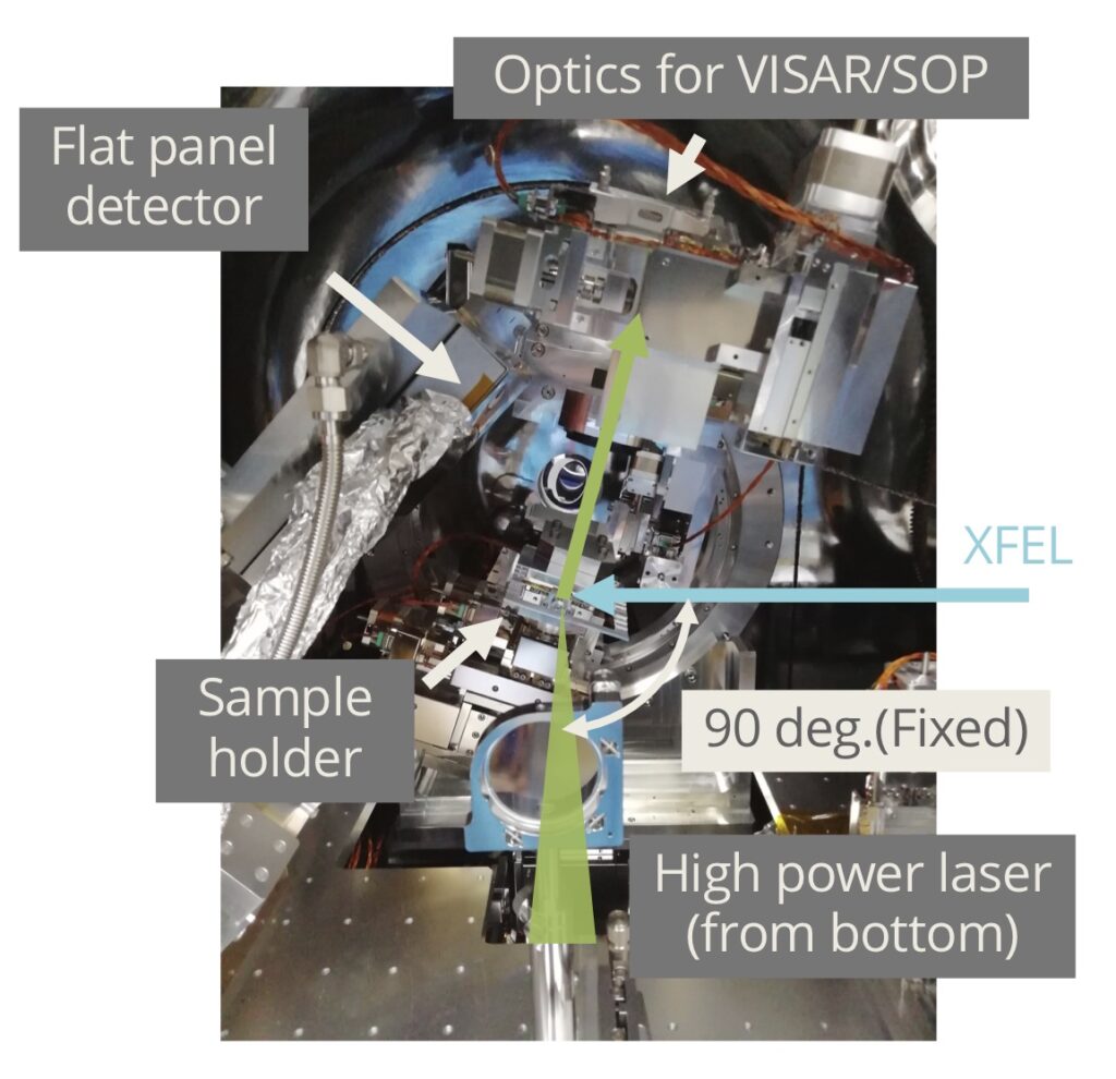
Inside the sample chamber
The driving mechanisms for the sample and the sample holder
A multi-axis stage for aligning the sample is permanently installed in the sample chamber.
The standard sample holder system consists of a strip-shaped sample plate (100 mm × 10 mm) that secures the sample and a frame that holds the sample plate. The frame is connected to the drive mechanisms by a magnetic kinematic base. The sample holder system can be modified to suit the experiment.
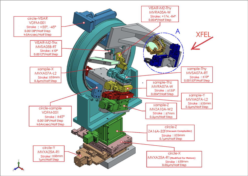
Driving mechanisms inside of the sample chamber

Details of the driving mechanism A inside of the sample chamber
Operating Parameters (EH5@BL3)
XFEL parameters
| Photon energy (fundamental wave) | 4-20 keV |
| Pulse energy | To photon energy (see figure below) |
| Energy width(ΔE/E) | ~0.5%(without a two crystal spectrometer) |
| Repetition rate | 30 Hz(BL2&3 simultaneous operation) |
References:
M. Yabashi et al., J. Synchrotron Rad. 22, 477 (2015).
K. Tono et al., J. Synchrotron Rad. 26, 595 (2019).
(Reference) The relationship between photon energy and pulse energy / number of photons (for BL3)

X-ray focusing characteristics
To ensure the resolution of X-ray diffraction, adjust the focusing size of the XFEL according to the experiment by using the following KB mirror optical system designed to have a vertical divergence angle of 1 mrad or less. In addition, X-ray can be focused in one direction by using only one side of the mirror.
The typical non-focused XFEL beam diameter is 600 µm (full width at half maximum), and can be adjusted to any size with the four-quadrant slit.
| Optical parameters (KB mirrors) | Vertical | Horizontal |
| Surface coating | Rhodium | Rhodium |
| Substrate size | 300 × 50 × 50 mm | 400 × 50 × 50 mm |
| Glancing angle | 4.0 mrad | 3.7 mrad |
| Focal length | 1200 mm | 800 mm |
| Distance from source | ~260 m | ~260 m |
| Spatial acceptance | > 1.2 mm | > 1.4 mm |
| Divergent angle | ~1 mrad | ~2 mrad |
| Typical focal size @10keV | ~430 nm FWHM | ~480 nm FWHM |
References:
Y. Inubushi et. al., Appl. Sci. 10, 2224 (2020).
Optical laser characteristics
| High-Power Nanosecond Laser | |
| Wavelength | 532 nm |
| Pulse Energy (Max.) | ~60 J(10 ns rectangular wave)* |
| Pulse Duration | 3-10 ns |
| Rep. Rate | 0.1 Hz |
* The maximum energy depends on the pulse waveform
Standard Experimental Arrangement
Examples of X-ray measurement methods and experimental arrangements
X-ray diffraction
・Wide-angle X-ray diffraction measurements for a sample irradiated with a high-power nanosecond laser using XFEL as a probe
・A flat panel detector (scintillation CMOS camera) can be installed inside the sample chamber, or a Dual-MPCCD can be installed outside of the chamber to be used as the detector
・When using a flat panel detector, it is possible to measure in both reflection and transmission arrangements

Small-angle X-ray scattering
- Small-angle X-ray scattering measurements from samples irradiated with a high-power nanosecond laser using XFEL as the probe
- ・A detector is installed downstream of the sample chamber
X-ray imaging
- ・Imagine measurements of a sample irradiated with a high-power nanosecond laser using XFEL as a probe
- ・A detector is installed downstream of the sample
Examples of optical measurement methods and experimental arrangements
Velocity interferometer measurements (VISAR)
- ・Velocity measurements for a sample irradiated with a high-power nanosecond laser using an optical laser as a probe
- ・The optical systems installed on the rotation stage(Circle stage, θx)of the diffractometer can be used
Radiance thermometer (SOP)
- ・Self-luminous thermometer measurements from a sample irradiated with a high-power nanosecond laser
- ・The optical system installed on the rotation stage(Circle stage, θx)of the diffractometer can be used
Adjustments before the Measurement
What the SACLA staff do before the beam time:
- ・Introduce the high-power nanosecond laser into the sample chamber
- ・Set up the facility equipment and perform the initial alignments
- ・Adjust and focus the XFEL spectrum and the optical axis
- ・Rough space matching between the XFEL and the high-power nanosecond laser
- ・Time matching of the XFEL and the high-power nanosecond laser using high-speed PD
What the user does after the start of the beam time:
- ・Precise space matching between the XFEL and the high-power nanosecond laser
- ・Precise alignment of the permanent equipment
- ・Precise alignment of user provided equipment
- ・Precise time matching between the XFEL and high-power nanosecond laser instruments
- ・Sample alignment
- ・XFEL and high-power nanosecond laser irradiation
- ・Operate the measurement equipment
Measurement Procedure
After the initial beam time adjustments are complete, the experiment is typically performed with the following procedure.
- 1. Install the sample in the sample chamber
- 2. Vacuum the sample chamber
- 3. Determine the interaction point between the high-power nanosecond laser and the sample
- 4. Pointing adjustments of the high-power nanosecond laser
- 5. Adjust the measurement equipment
- 6. Align the sample
- 7. Perform the data acquisition shot
- 8. Open the sample chamber to the atmosphere
Data from the SACLA standard detectors can be accessed using the SALCA HPC.
Related Results
Press release
Papers published
What to check before applying for an assignment
If you are planning an experiment using the high-power nanosecond laser introduced on this page, and the available laser conditions apply, please contact the このメールアドレスはスパムボットから保護されています。閲覧するにはJavaScriptを有効にする必要があります。 before applying for an assignment.