500TWレーザー(高エネルギー密度科学)
XFELと最大出力500TWのハイパワーフェムト秒レーザーを同時に利用することで、例えばハイパワーレーザーが作り出す極限環境を超高速に診断することが可能となります。本ページでは、相互利用実験施設内のBL2 EH6におけるハイパワーフェムト秒レーザー利用実験について紹介します。
参考文献:
T. Yabuuchi et al., J. Synchrotron Rad. 26, 585 (2019).
基本性能・成果
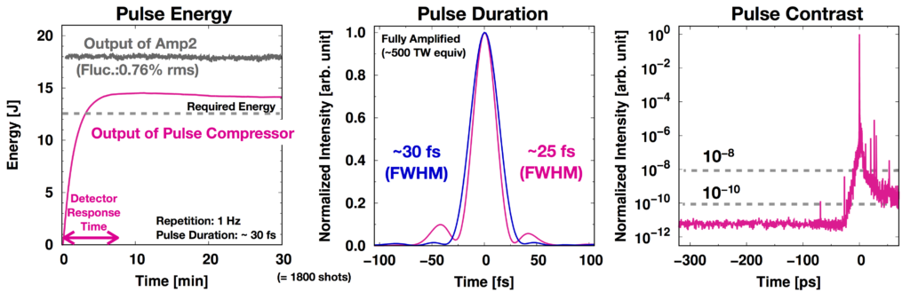
ハイパワーフェムト秒レーザー特性
ハイパワーフェムト秒レーザーの標準的な運転条件における特性を、下図にまとめました。左から順に、エネルギー安定性、パルス幅、時間コントラストの測定例です。

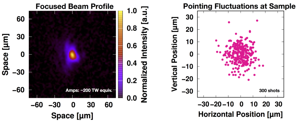
ハイパワーフェムト秒レーザー集光特性
下図では、定格エネルギーである10 J級まで増幅したレーザーを減衰させ、パルス圧縮器で40 fs程度まで圧縮した後に、焦点距離1.2 mの軸外し放物面鏡で集光した際の集光スポット像とその重心位置の揺らぎを示しています。

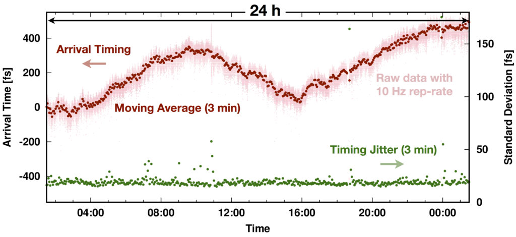
XFEL-レーザー時間同期特性
XFELとレーザーのサンプル位置での時間同期精度に関しては、短時間(3分間)の測定ではおよそ20 fs (rms)が達成されています。一方で、長時間の測定では数百 fs/h程度のドリフトが確認されており、このドリフト抑制に向けた開発・試験が現在進められています。
実験装置
試料チャンバー
ハイパワーフェムト秒レーザーを用いた実験では、実験ハッチ内に常設されている大型真空チャンバー内にサンプルを設置します。この試料チャンバー内でハイパワーフェムト秒レーザーとXFELがサンプルに照射されます。
試料チャンバー概観
 ー 試料チャンバー内部 セットアップ例(右手に見えるのがf1.2m軸外し放物面鏡)
サンプル駆動機構及びサンプルホルダー
試料チャンバー内には、固体サンプルを保持、調整するための駆動機構が常設されています。ハイパワーレーザーを使用した典型的な実験では、固体サンプルは1ショットで破壊されるため、ショットの都度サンプルをレーザー照射位置(レーザー-サンプル相互作用点)に設置することが必要です。
個々の固体サンプルは、有効エリアが3 cm四方のサンプルホルダーに固定して、駆動機構最上部の円盤型サンプルプレートに取り付けます。サンプルホルダーは、サンプルプレートに最大5または6枚を同時に取り付けることができます。サンプルホルダーは、実験に使用されるサンプルの形状や特性、また計測器の配置などに応じて適切に設計・製作される必要があります。
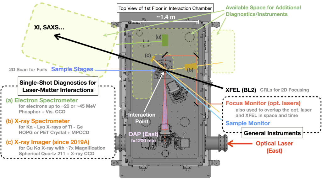
施設整備の標準計測器
発光X線スペクトロメーター
・XFELまたはレーザーのサンプルへの照射により発生するX線のスペクトル測定に使用。
・大気中に設置されたMPCCDを検出器として使用。
・真空中の電動ステージに取り付けたPETまたはHOPG(高配向性熱分解グラファイト)をX線分光結晶として使用。
・分光結晶位置を変えることで、検出波長範囲を選択(対応波長域はおおよそTi〜GeのKα〜Lyαの一部)。
球面結晶X線イメージャー
- ・XFELまたはレーザーの銅サンプルへの照射により発生する銅のKαX線のイメージングに使用。
- ・結像には、真空中に設置された球面石英結晶(R = 500 mm)を使用し、倍率は約7倍。
- ・検出器には、大気中に設置された直接照射型X線CCDカメラを使用。
高エネルギー電子スペクトロメーター
・ハイパワーフェムト秒レーザーのサンプルへの高強度照射により発生するMeV級の高エネルギー電子のエネルギースペクトル測定に使用。
・エネルギー測定領域は、数MeVから最大40 MeV程度まで対応。
・磁気回路にて偏向された電子が蛍光体に突入した際の蛍光像を、大気中に設置した可視CCDカメラで撮像することで、シングルショットでのスペクトル測定が可能。
運転パラメータ(EH6@BL2)
XFELパラメータ
| 光子エネルギー(基本波) | 4-20 keV |
| パルスエネルギー | 光子エネルギーに依存(下図参照) |
| エネルギー幅(ΔE/E) | ~0.5%(ニ結晶分光器なし) |
| 繰り返しレート | 30 Hz(BL2&3同時運転時) |
参考文献:
M. Yabashi et al., J. Synchrotron Rad. 22, 477 (2015).
K. Tono et al., J. Synchrotron Rad. 26, 595 (2019).
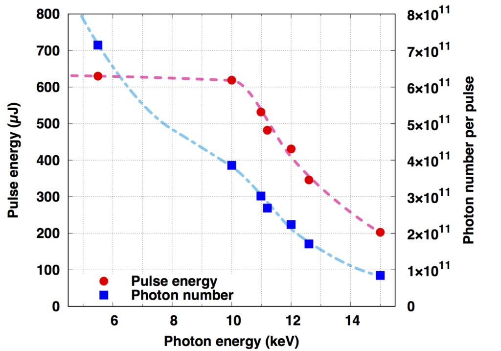
(参考)光子エネルギーとパルスエネルギー・光子数の関係(BL3の場合)
X線集光特性
下記のCRLsを利用することで、XFELと500TWレーザーの光軸交点上に試料を固定したまま、実験に合わせて試料上の集光X線ビームのスポット径を調整することが可能です。
| Optical parameters (CRLs) | |
| Material | Beryllium |
| Shape of lenses | Paraboloid |
| Radii of curvatures (R) | 500, 1000, 1500, 2000 µm |
| Maximum number of lenses | 63 with R = 500 µm 3 with R = 1000 µm 3 with R = 1500 µm 3 with R = 2000 µm |
| Focal length | 3 m |
| Spatial acceptance | > 1.3 mm |
| Divergent angle | > 0.2 mrad* |
| Typical focal size @10 keV | ~3 µm FWHM* |
*使用するレンズの数や波長に依存します。
参考文献:
T. Yabuuchi et al., J. Synchrotron Rad. 26, 585 (2019).
光学レーザー特性
| ハイパワーフェムト秒レーザー | |
| Wavelength | 800 nm |
| Pulse Energy (Max.) | ~10 J* |
| Pulse Duration (Typ.) | ~40 fs |
| Rep. Rate | 1 Hz |
*記されているエネルギーはパルス圧縮前の値です。
標準的な実験配置
これまでに実施されたX線計測手法と実験配置の例
イメージング計測
・XFELをプローブ光とした、ハイパワーフェムト秒レーザー照射サンプルのX線イメージング。
・間接照射型高分解能X線カメラまたは持ち込みX線CCDカメラなどの高いピクセル分解能を有する検出器を使用。
・必要に応じてCRLによる集光XFELの利用と、検出器をサンプルから遠方(最大4m)に設置することが可能。
散乱計測
・XFELをプローブ光とした、ハイパワーフェムト秒レーザー照射サンプルからの散乱X線計測。
・大気中で大面積(2チップ)のMPCCDカメラを使用。
・散乱XFELの測定領域は、試料から最短1mの位置にある真空ウィンドウで制限される(実績のあるBe窓付き真空フランジの寸法はICF152、有効開口は75mm)。
分光計測
- ・ハイパワーフェムト秒レーザー照射サンプルによるXFELプローブ光のスペクトル変調計測。
- ・試料チャンバー下流側にて高分解能なX線分光器を設置。
標準計測器以外の計測器類の設置
試料チャンバー内またはその周辺に実験ごとに必要な装置を配置することが可能です。ただし、XFELや光学レーザーの調整に必要な装置や既存の標準計測機器との干渉などがない配置をとる必要があります。
また、SACLA保有の装置以外に独自の装置を持ち込まれる場合、特に真空チャンバー内に持ち込み装置を設置することを希望される場合は、使用可能な機器の仕様に条件があります。
したがって、実験セットアップの検討及び使用装置の評価、決定に長時間を要する場合があります。持ち込み装置の有無に関わらず、希望されるセットアップのフィージビリティについては、課題申請前にXFEL利用研究推進室(このメールアドレスはスパムボットから保護されています。閲覧するにはJavaScriptを有効にする必要があります。)までお問い合わせください。
作業分担および測定までの調整作業
基本的にSACLAのスタッフが行うこと
- ・施設側計測器初期アライメント
- ・XFELビームライン調整(スペクトル測定、光軸調整)
- ・ハイパワーフェムト秒レーザー光路調整
- ・XFEL初期集光調整
- ・ハイパワーフェムト秒レーザー集光調整
- ・ハイパワーフェムト秒レーザー-サンプル相互作用点決定
- ・XFEL-ハイパワーレーザータイミング調整(GaAsを用いた時間原点の決定)
- ・ハイパワーレーザーエネルギー調整
- ・試料チャンバー真空排気、大気開放
基本的にユーザーが行うこと
- ・持ち込み装置設置・アライメント
- ・常設装置・計測器精密アライメント
- ・サンプルアライメント
- ・サンプルへのXFEL及びハイパワーレーザー照射
- ・XFELの輝度調整
測定開始までの事前準備・初期調整(ビームタイム初期)
- ・ハイパワーフェムト秒レーザーの調整(実験に使用するレーザー条件に適したパラメータ確認など)
- ・施設側計測器の設置、調整
- ・ユーザー持ち込み装置の設置、調整
- ・XFEL、ハイパワーフェムト秒レーザーの試料チャンバー内への導入
- ・XFELの集光スポット測定
- ・高速PDを用いたXFELとハイパワーフェムト秒レーザーの時間同期
- ・サンプルアライメント手法の確認、確立
- ・計測器・装置の動作確認、信号確認
測定手順
定常モードでのサイクル(1日毎または試料チャンバー開放毎)
現在のところ、ハイパワーフェムト秒レーザーを利用した実験では、ビームタイム開始後の初期調整が終わった後も、施設側担当者が行う作業とユーザーが行う作業が継続して発生します。試料チャンバー内に一度に設置できるサンプル数や実験条件維持の観点から、ユーザーのデータ取得ショットが開始された後は、およそ1日(2シフト)を基準とした以下のサイクルで実験が行われています。特に、このうち6-8の作業については、実施可能な時間を原則10am-10pmの間に限定しています。
- 1. 試料チャンバー内サンプル駆動機構へのサンプル取り付け
- 2. 試料チャンバー真空引き
- 3. XFEL集光調整
- 4. ハイパワーフェムト秒レーザーとサンプルの相互作用点決定
- 5. サンプルアライメント
- 6. ハイパワーフェムト秒レーザー立ち上げ、集光調整
- 7. XFELとハイパワーフェムト秒レーザーの時間原点決定
- 8. データ取得ショット
- 9. 試料チャンバーパージ
サンプル事前アライメント
個々の固体サンプルを連続してショットするため、データ取得ショットに先立って、個々のサンプルをアライメントし、そのステージ位置を記録します。サンプルのアライメントには、XFEL、ハイパワーレーザーと同軸のアライメント光(800 nm LD)を光源とし、各種カメラを使用することができます。
データ取得ショット
XFELとハイパワーフェムト秒レーザーを使用したデータ取得ショットは、ユーザー自身による操作で実施します。この標準的な作業に対応した以下の各種スクリプトが用意されています。基本的な検出器はショットに同期したトリガーにより動作し、そのデータにはSACLAのHPCを利用してアクセスすることが可能です。(持ち込み検出器、間接照射型高分解能X線カメラなどはローカルPC上での制御、データ保存となります。)
- ・事前アライメントで決定した位置にサンプルを移動
- ・XFEL単独のシングルまたはマルチショットを実施
- ・ハイパワーフェムト秒レーザー単独のシングルショットを実施
- ・XFEL及びハイパワーフェムト秒レーザーの同時シングルショットを実施
500TW laser (High Energy Density Science)
By simultaneously using XFEL and high-power femtosecond lasers with a maximum output of 500TW, it is possible to diagnose extreme environments created, by example, from high-power lasers at ultra high-speeds. This page will introduce the high-power femtosecond laser experiments in the mutual experimental facility at BL2 EH6.
References:
T. Yabuuchi et al., J. Synchrotron Rad. 26, 585 (2019).
Basic Performance and Results
High-power femtosecond laser characteristics
The characteristics of the high-power femtosecond laser under standard operating conditions are summarized in the figure below. From left to right are examples of the measured energy stability, pulse width and time contrast.
High-power femtosecond laser characteristics
In the figure below, the fluctuation of the image and the center of gravity are shown. This is done by attenuating the amplified laser to the rated value energy of 10 J, then compressing to approximately 40 fs with a pulse compressor, as well as focusing the laser with an off-axis parabolic mirror with a focal length of 1.2m.
XFEL laser time synchronization characteristics
For time synchronized accuracy between XFEL and the laser sample position, approximately 20 fs(rms) has been achieved for short (3 minute) measurements. On the other hand, drift of several hundred fs/h has been confirmed for long-term measurements, and developments and tests are currently underway to suppress this drift.
Experimental Equipment
Sample chamber
For experiments using a high-power femtosecond laser, the sample is placed in a large vacuum chamber that is permanently installed in the experimental hatch. The sample is irradiated with a high-power femtosecond laser and XFEL inside the sample chamber.

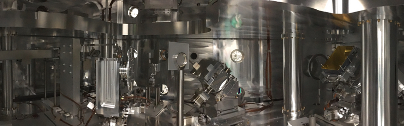
Example of the internal setup of the sample chamber (f1.2m off-axis parabolic mirror is visible on the right)
The driving mechanisms for the sample and the sample holder
In the sample chamber, a driving mechanism is permanently installed to hold and adjust solid samples. In a typical experiment with a high-power laser, a solid sample is destroyed in one shot, so it is necessary to install the sample at the laser irradiation position (laser-sample interaction point) for each shot.
Individual solid samples are mounted on a disk-shaped plate at the top of the driving mechanism and secured in the sample holder which has an effective area of 3 cm square. The sample holder can be installed on the sample plate and can hold up to 5 or 6 samples at a time. The sample holder must be properly designed and manufactured according to the shape and characteristics of the sample used in the experiment, as well as the placement of the equipment.
Standard measurement equipment for facility maintenance
Emission X-ray spectrometer
・Used to measure the spectrum of X-rays generated by irradiating the sample with XFEL or lasers
・The MPCCD installed in the atmosphere is used as a detector
・PET or HOPG (Highly Oriented Pyrolytic Graphite), which are attached to the electric stage in the vacuum, are used as X analyzer crystals
・By changing the analyzer crystal position, the detection wavelength range can be selected (the corresponding wavelength ranges selected are Kα〜Lyα of Ti〜Ge)
Spherical crystal X-ray imager
- ・Used for imaging copper KαX rays generated by irradiating copper samples with XFEL or lasers
- ・For imaging, spherical quartz crystals (R = 500 nm) installed in the vacuum are used, and the magnification is approximately 7 times
- ・For the detector, a direct irradiation X-ray CCD camera is used, and is installed in the atmosphere
High-energy electron spectrometer
・This is used for measuring the energy spectrum of MeV-class high-energy electrons generated by high-intensity irradiation of high-power femtosecond laser samples
・The area supported for the energy measurements are from several MeV to a maximum of approximately 40 MeV
・A single-shot spectrum measurement is possible by capturing the fluorescence image, which happens when electrons deflected by the magnetic circuit enter the phosphor, with a visible CCD camera installed in the atmosphere
Operating Parameters (EH6@BL2)
XFEL parameters
| Photon energy (fundamental wave) | 4-20 keV |
| Pulse energy | To photon energy (see figure below) |
| Energy width(ΔE/E) | ~0.5%(without a two crystal spectrometer) |
| Repetition rate | 30 Hz(BL2&3 simultaneous operation) |
References:
M. Yabashi et al., J. Synchrotron Rad. 22, 477 (2015).
K. Tono et al., J. Synchrotron Rad. 26, 595 (2019).
(Reference) The relationship between photon energy and pulse energy / photon number (In the case of BL3)

X-ray focusing characteristics
By using the following CRL, it is possible to adjust the spot diameter of the focused X-ray beam on the sample according to the experiment while keeping the sample fixed on the optical axis intersection of the XFEL and 500TW laser.
| Optical parameters (CRLs) | |
| Material | Beryllium |
| Shape of lenses | Paraboloid |
| Radii of curvatures (R) | 500, 1000, 1500, 2000 µm |
| Maximum number of lenses | 63 with R = 500 µm 3 with R = 1000 µm 3 with R = 1500 µm 3 with R = 2000 µm |
| Focal length | 3 m |
| Spatial acceptance | > 1.3 mm |
| Divergent angle | > 0.2 mrad* |
| Typical focal size @10 keV | ~3 µm FWHM* |
*Depending on the number of lenses used and the wavelength.
References:
T. Yabuuchi et al., J. Synchrotron Rad. 26, 585 (2019).
Optical laser characteristics
| High-Power Femtosecond Laser | |
| Wavelength | 800 nm |
| Pulse Energy (Max.) | ~10 J* |
| Pulse Duration (Typ.) | ~40 fs |
| Rep. Rate | 1 Hz |
*The energy shown is the value before the pulse compression.
Standard Experimental Configuration
Examples of X-ray measurement methods and experimental arrangements conducted so far
Imaging measurements
・X-ray imaging of high-power femtosecond laser irradiation samples using XFEL as the probe light
・Using a detector with high-pixel resolution, such as a indirect irradiation high-resolution X-ray camera, or a user provided X-ray CCD camera
・If necessary, the CRL can use the focused XFEL, and the detector can be installed far from the sample (up to 4 m)
Scattering measurements
・Scattered X-ray measurements from a high-power femtosecond laser irradiation sample using XFEL as the probe light
・A large area (2 chip) MPCCD camera used in the atmosphere
・The measurement area of the scattered XFEL is limited by a vacuum window located at a minimum distance of 1 m from the sample (the achieved Be window vacuum flange is ICF152, and the effective opening is 75 mm)
Spectrometer
- ・Spectral modulation measurements of XFEL probe light using a high-power femtosecond laser irradiation sample
- ・A high-resolution X-ray spectrometer is installed downstream of the sample chamber
Installing measurement equipment other than the standard measurement equipment
It is possible to place the necessary equipment for each experiment in or around the sample chamber. However, it is necessary to arrange them so that it does not interfere with the equipment required for adjusting the XFEL, optical lasers and existing standard measurement equipment.
In addition, if you bring in your own equipment other than the equipment owned by SACLA, and you wish to install the equipment in a vacuum chamber, there are conditions for the specifications of the equipment that can be used.
Therefore, it may take a long time to consider the experimental setup and evaluate and determine the equipment to be used. Please contact the XFEL Utilization Division (このメールアドレスはスパムボットから保護されています。閲覧するにはJavaScriptを有効にする必要があります。) before applying for the assignment for details on the feasibility of the user provided equipment setup.
Work Shared and Adjustments before the Measurement
What the SACLA staff perform:
- ・Initial alignments of the facility measurement equipment
- ・XFEL beamline adjustments (spectral measurements, optical axis adjustments)
- ・High-power femtosecond laser optical path adjustments
- ・Initial XFEL focusing adjustments
- ・High-power femtosecond laser focusing adjustments
- ・High-power femtosecond laser – sample interaction point determination
- ・XFEL-High power laser timing adjustments (determine the time origin using GaAs)
- ・High-power laser energy adjustments
- ・Sample chamber vacuum exhaust, and opening to the atmosphere
What the users perform:
- ・Install and align the user provided equipment
- ・Precision alignment of permanent and measurements equipment
- ・Sample alignments
- ・XFEL and high-power laser irradiation of the sample
- ・XFEL brightness adjustments
Preparation and initial adjustments before the start of the measurements (initial beam time)
- ・High-power femtosecond laser adjustments (confirming the parameters suitable for the laser conditions used in the experiments, etc.)
- ・Install and adjust the facility-side measuring equipment
- ・Install and adjust the user provided equipment
- ・Introduce the XFEL and high-power femtosecond laser into the sample chamber
- ・XFEL focusing spot measurements
- ・Time synchronization between the XFEL and the high-power femtosecond laser using high-speed PD
- ・Confirm and establish the sample alignment methods
- ・Confirm the operation and signal of the measuring equipment and devices
Measurement Procedure
Cycle in steady mode (every day or every time the sample chamber is opened)
Currently, in experiments using high-power femtosecond lasers, the work performed by the facility staff and the work performed by the user continue to occur even after the initial adjustment at the start of the beam time. To maintaining the experimental conditions and number of samples and that can be installed in the sample chamber at a time, after the user’s data acquisition shot is started, the experiment is conducted based on the following cycle of 1 day (2 shifts). In particular, for 6-8 of these tasks, the available time is limited to 10am to 10pm, in principle.
- 1. Attach the sample to the sample driving mechanism in the sample chamber
- 2. Evacuate the sample chamber
- 3. XFEL focusing adjustments
- 4. Determine the interaction point between the high-power femtosecond laser and the sample
- 5. Sample alignments
- 6. High-power femtosecond laser start-up, focusing adjustments
- 7. Determine the XFEL and high-power femtosecond laser time origin
- 8. Data acquisition shot
- 9. Purge the sample chamber
Sample pre-alignment
Because individual solid samples are shot in succession, the individual samples are aligned, and their stage positions are recorded prior to the data acquisition shot. Various cameras can be used for sample alignment with XFEL, high-power lasers and coaxial alignment light (800 nm LD) as the light source.
Data acquisition shot
Data acquisition shots using XFEL and high-power femtosecond lasers are performed by the user. The following scripts are available to support the standard tasks. The basic detector works with triggers synchronized to the shot, and the data can be accessed using the SACLA HPC (user provided detectors, indirect irradiation high-resolution X-ray cameras and the like are controlled on local PCs, where the data is saved).
- ・Move the sample to the position determined by pre-alignment
- ・Perform single or multi-shot XFEL
- ・Perform a high-power femtosecond laser single shot
- ・Perform simultaneous single shots of XFEL and high-power femtosecond lasers