- 詳細
- 投稿者: Super User
- カテゴリ: 設備
- 参照数: 667
マイクロ・ナノビームX線回折装置
◆装置概要
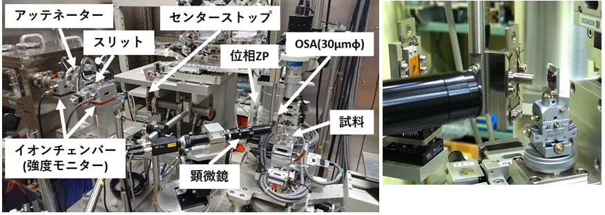
本装置は、集光素子を用いてX線を200nm~数μmに集光し、このマイクロ・ナノビームX線を用いて高い角度分解能で結晶の局所歪やその分布を調べることができる装置です。

◆装置の特徴
本装置は、X線を200nm~数μmに集光し、これを用いたX線回折測定を行うことで結晶の局所歪やその分布を調べることができる装置です。集光素子には、X線のエネルギーに応じてフレネルゾーンプレートと屈折レンズを選択することができます。使用可能なX線エネルギーは8~35keV、ビームサイズは200nm~数μm、ビーム強度はおよそ109~1010photon/sec程度です。また、逆格子マップ測定を迅速に行うために、高感度な2次元検出器を整備しています。集光光学系
15 keV以下のX線の集光素子としてフレネルゾーンプレート、15 keV以上のX線用に屈折レンズを備えています。これらの集光素子により、8~35keVのX線において200nm~数μmにX線を集光することが可能です。
検出器
本装置の検出器にはハイブリッド型多次元ピクセル検出器HyPix-3000(株式会社リガク製)、ピクセル型検出器TimePix(Amsterdam Scientific Instruments社製)が用意されています。また、蛍光X線を用いた試料位置出しや元素分析のために、Si PIN検出器XR-100CRおよびCdTe検出器XR-100CdTeを備えています。
制御ソフトウェア
装置の制御には、LabView(National Instruments社製)によって開発されたソフトウェアを用いています。強度分布測定や逆格子マップ測定といった測定は自動化されており、パラメータの設定のみで長時間の連続測定が可能です。
◆装置アクセサリー
本装置では、下記のアクセサリーが利用可能です。
・X線チョッパー
実験に必要な周期のパルスX線のみを取り出すことにより、ポンプ-プローブ法などの測定が可能です。
・ダイヤモンド位相子
入射X線の偏光を回転させることにより、水平面内での散乱配置において散乱角90度付近の回折X線の観測が可能です。
◆実験・試料準備
・測定可能な試料サイズは最大でおよそ横幅10 mm,縦幅 20 mm程度,厚さは 5 mm 程度です。
・試料マウントへの試料の取り付けは、主に両面テープ等を用いて行っています。
・試料周辺の作業空間が限られますので、ポンプ-プローブ法など試料周辺に測定装置を設置する必要がある場合は事前に担当者にご連絡ください。
◆実験手順・注意事項
測定手順
1. 試料を試料マウントに取り付けます。
2. ハッチ内の測定装置と同じ状態になるよう調整したオフライン試料位置調整用ステージで、試料アライメントと測定位置の調査を行います。
3. 測定装置に試料を取り付け、半割りによる試料位置調整を行います。
4. 試料の角度ωと検出器の角度2θを動かして、回折X線を見つけます。
5. 回折条件の付近でωスキャンを行い、逆格子マップ測定を行います。
6. 試料YZステージを用いてビーム照射位置を調整し、順次測定を行います。
注意事項
・試料の特定の位置に精度良くX線を照射する場合は、PtやAuなどのマーカーを試料上に作製しておくことをお勧めします。測定では、蛍光X線の観測によりこのマーカー位置を特定し、そこからの相対位置で試料位置を調整します。
◆問い合わせ先
今井 康彦 (このメールアドレスはスパムボットから保護されています。閲覧するにはJavaScriptを有効にする必要があります。)
隅谷 和嗣 (このメールアドレスはスパムボットから保護されています。閲覧するにはJavaScriptを有効にする必要があります。)
◆代表的な論文リスト
“Quantitative Analysis of Lattice Plane Microsctructure in the Growth Direction of a Modified Na-Flux GaN Crystal using Nanobeam X-ray Diffraction”
Kazuki Shida, Nozomi Yamamoto, Tetsuya Tohei, Masayuki Imanishi, Yusuke Mori, Kazushi Sumitani, Yasuhiko Imai, Shigeru Kimura and Akira Sakai
Japanese Journal of Applied Physics, 58, (2019) SCCB16
10.7567/1347-4065/ab0d05
“Current Status of Nanobeam X-ray Diffraction Station at SPring-8”
Yasuhiko Imai, Kazushi Sumitani, and Shigeru Kimura
AIP Conference Proceedings, 2054, (2019) 050004
“Compound Refractive Lens Optics for Microbeam X-ray Diffraction Measurements at BL13XU in SPring-8”
Kazushi Sumitani, Yasuhiko Imai and Shigeru Kimura
Microscopy and Microanalysis, 24, (2018) 302-303.
“Synchrotron Radiation Microbeam X-ray Diffraction for Nondestructive Assessments of Local Structural Properties of Faceted InGaN/GaN Quantum Wells”
Atsushi Sakaki, Mitsuru Funato, Tomoaki Kawamura, Jun Araki and Yoichi Kawakami
Applied Physics Express, 11, (2018) 031001
“Characterization of domain structure in one-dimensional SrRuO3 nanostructure using synchrotron x-ray microdiffraction”
Yasuhiko Imai, Shigeru Kimura, Daisuke Kan and Yuichi Shimakawa
AIP Conference Proceedings, 1741, (2016) 050014
Micro and Nanobeam X-Ray Diffraction Equipment
◆Equipment overview
This equipment uses focusing elements to collect X-rays from 200nm to several μm. These micro and nanobeam X-rays are used in order to investigate local crystal strains and their distribution with high angular resolution.

◆Features of the Equipment
This equipment uses X-rays collected from 200nm to several μm for X-ray diffraction measurements to investigate local strains and distributions of crystals. For the focusing elements, a Fresnel zone plate or refractive lenses can be selected according to the X-ray energy. The available X-ray energy ranges from 8~35keV, with the beam size from 200nm to several μm, and the beam intensity ranges up to approximately 109~1010photon/sec. In addition, a high-sensitivity 2-dimensional detector has been developed for rapid reciprocal lattice mapping measurements.Concentration Optical Systems
For X-rays of 15 keV, a Fresnel zone plate is used, and for X-rays 15 keV or more, refraction lenses are used. These focusing elements enable X-rays of 200nm~severalμm in the range of 8~35keV to be collected.
Detector
The detector equipment prepared contains a hybrid multi-dimensional pixel detector HyPix-3000 (made by Rigaku Co), and a pixel detector TimePix (made by Amstredam Scientific Instruments). It also features X-ray fluorescence for sample positioning and elemental analysis with the use of an Si PIN detector XR-100CR and a CdTe detector XR-100CdTe.
Control Software
Software developed by LabView (made by National Instruments) is used to control the equipment. Measurements such as intensity distribution and reciprocal lattice map measurements are automated, and long-term, continuous measurements are possible by setting parameters.
◆Equipment accessories
The following accessories are available for these devices:
・X-ray chopper
By taking out the necessary periodic pulse X-rays in the experiment, it is possible to measure with the pump-probe method and the like.
・Diamond Phase Retarder
By rotating the incident polarized X-rays, X-rays with a scattering angle of around 90 degrees can be observed within the scattering arrangement in the horizontal plane.
◆Experiment / sample preparation
・The measurable sample size is approximately 10mm wide, 20mm long, and 5mm thick.
・To attach the sample to the sample mount, double-sided tape is commonly used.
・Since the work space around the sample is limited, please contact the person in charge in advance if you need to install a measuring device around the sample, such as a the pump-probe method.
◆Experimental procedure / precautions
Measurement Procedure
1. Attach the sample to the sample mount.
2. Adjust the offline sample location adjustment stage to the same state as the measurement devices inside the hatch to investigate the sample alignment and measurement location.
3. When the sample is installed in the measurement device, adjust the sample location at half rate.
4. Move the sample ω angle and the detector 2θ angle to observe the diffraction X-rays.
5. A ω scan is performed in the neighborhood of the diffraction conditions to perform reciprocal lattice map measurements.
6. The beam irradiation position is adjusted using the sample YZ stage, and sequential measurements are performed.
Notes
・When accurately irradiating X-rays at the specific sample position, it is recommended that markers such as Pt and Au be used with the sample. During the measurement, the marker position is identified by the observation of fluorescence X-rays, and the position of the sample is adjusted from the relative positioning.
◆Contact
今井 康彦 (このメールアドレスはスパムボットから保護されています。閲覧するにはJavaScriptを有効にする必要があります。)
隅谷 和嗣 (このメールアドレスはスパムボットから保護されています。閲覧するにはJavaScriptを有効にする必要があります。)
◆List of representative treatises
“Quantitative Analysis of Lattice Plane Microsctructure in the Growth Direction of a Modified Na-Flux GaN Crystal using Nanobeam X-ray Diffraction”
Kazuki Shida, Nozomi Yamamoto, Tetsuya Tohei, Masayuki Imanishi, Yusuke Mori, Kazushi Sumitani, Yasuhiko Imai, Shigeru Kimura and Akira Sakai
Japanese Journal of Applied Physics, 58, (2019) SCCB16
10.7567/1347-4065/ab0d05
“Current Status of Nanobeam X-ray Diffraction Station at SPring-8”
Yasuhiko Imai, Kazushi Sumitani, and Shigeru Kimura
AIP Conference Proceedings, 2054, (2019) 050004
“Compound Refractive Lens Optics for Microbeam X-ray Diffraction Measurements at BL13XU in SPring-8”
Kazushi Sumitani, Yasuhiko Imai and Shigeru Kimura
Microscopy and Microanalysis, 24, (2018) 302-303.
“Synchrotron Radiation Microbeam X-ray Diffraction for Nondestructive Assessments of Local Structural Properties of Faceted InGaN/GaN Quantum Wells”
Atsushi Sakaki, Mitsuru Funato, Tomoaki Kawamura, Jun Araki and Yoichi Kawakami
Applied Physics Express, 11, (2018) 031001
“Characterization of domain structure in one-dimensional SrRuO3 nanostructure using synchrotron x-ray microdiffraction”
Yasuhiko Imai, Shigeru Kimura, Daisuke Kan and Yuichi Shimakawa
AIP Conference Proceedings, 1741, (2016) 050014
