タイミングモニター
タイミングモニターとは、XFELパルスとフェムト秒レーザーの相対到達時間をショットごとに計測する装置です。この到達時刻情報をもとにポンプ・プローブ測定結果を並び替えることで時間ジッターの影響を排除し、数十フェムト秒の時間分解能を有する測定が可能となります。
タイミングモニターの原理
特定の薄膜試料にXFELが照射されると、フェムト秒レーザーの試料中の透過、及び、反射強度が過渡的に変化します。タイミングモニターはこの現象を利用しています。SACLAに常設されているタイミングモニターでは、XFELとフェムト秒レーザーの薄膜試料への入射角度差を45°程度に大きくとり、到達時間情報を空間に焼き直す空間ディコーディング法を用いることで、XFELとフェムト秒レーザーの相対時間差を測定します。薄膜試料には、厚み5 μm程度のGaAs(ヒ化ガリウム)を用います。試料にXFELが到達すると、その照射領域が励起され、フェムト秒レーザーの透過率、及び、反射率が低下します。この時、フェムト秒レーザーのGaAs透過像、又は、反射像をCCDカメラ等の2次元検出器で取得すると、XFELのパルスフロントがエッヂとして検出されます。この像をショットごとに取得し、解析を行います。十分な励起強度を確保するために、XFELビームは楕円ミラーで試料上に1次元集光しています。

タイミングモニターの光学配置(透過像検出)
タイミングモニターの構成
BL3用タイミングモニター
BL3におけるフェムト秒同期レーザーを用いたポンプ・プローブ実験で使用可能なタイミングモニターはEH1に常設されています。BL3 OHに設置された透過型回折格子を用いてXFELパルスを0、±1次の3本に分離し、0次光をユーザー実験に提供しながら、-1次光をタイミングモニタ計測に使用します。なお、+1次光はシングルショットスペクトロメーター用に利用できます。フェムト秒レーザーの一部もEH1に導入され、タイミングモニターのプローブ用に使用されます。
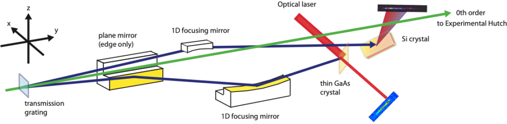
BL3におけるタイミングモニター
BL1用タイミングモニター
BL1におけるフェムト秒同期レーザーを用いたポンプ・プローブ実験で使用可能なタイミングモニターはEH4aに常設されています。ビームラインに設置された波面分割用楕円柱ミラーを用いてFELパルスを2本に分離し、一方をユーザー実験に提供しながら、もう一方をタイミングモニタ計測に使用します。測定データの解析には、BL3用タイミングモニターと同じソフトウェアが使用できます。
参考文献:
T. Sato et al., Appl. Phys. Express 8, 012702 (2015).
T. Katayama et al., Struct. Dyn. 3, 034301 (2016).
K. Nakajima et al., J. Synchrotron Rad. 25, 592 (2018).
S. Owada et al., J. Synchrotron Rad., 26, 887 (2019).
Timing Monitor
A timing monitor is a device that measures the relative arrival time of an XFEL pulse and femtosecond laser for each shot. By sorting the pump-probe measurements based on this arrival time information, the effect of time jitter can be eliminated, and measurements with a time-resolution of several tens of femtosecond become possible.
The principles of timing monitors
When a specific thin film sample is irradiated with XFEL, the transmission of the femtosecond laser through the sample and the reflection intensity change as it interacts with the sample. Timing monitors take advantage of this phenomenon. With the timing monitor permanently installed at SACLA, the difference in the incident angle between the XFEL and the femtosecond laser on the thin film sample is greatly increased to about 45°, and by using a spatial decoding method to signal the arrival time, the relative time difference between the XFEL and femtosecond laser can be measured. GaAS (Gallium Arsenide) with a thickness of approximately 5 μm is used for the thin film samples. When the XFEL reaches the sample, the irradiated area becomes excited, and the transmittance and reflectance of the femtosecond laser decreases. At this time, if the GaAS transmission or reflection image for the femtosecond laser is acquired by a two-dimensional detector such as a CCD camera, the pulse front of the XFEL will be detected as an edge. This image is acquired for each shot, then analyzed. To ensure sufficient excitation intensity, the XFEL beam is focused one-dimensionally on the sample with an elliptical mirror.
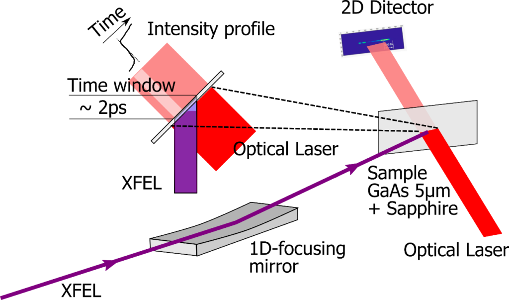
ー Optical arrangement of the timing monitor (Transmission image detection)
Timing monitor configuration
The timing monitor at BL3
The timing monitor that can be used for pump-probe experiments using a femtosecond synchronous laser at BL3 is permanently installed in EH1. Using a transmission diffraction lattice installed in BL3 OH, the XFEL pulses are separated into three orders, 0 and ±1, then the separated 0th order light is used for user experiments, and the -1 is primarily used for timing monitor measurements. The +1 can be used for single shot spectrometers. Some femtosecond lasers have been introduced into the EH1 and are used for timing monitor probes.

The timing monitor at BL3
The timing monitor at BL1
The timing monitor that can be used for pump-probe experiments using a femtosecond synchronous laser at BL1 is permanently installed in EH4a. An elliptical column mirror permanently installed at the beamline is used to separate the wave surface of the FEL pulses into two, one for the timing monitor measurements and the other for the user experiments. The same software used for the timing monitor at BL3 can be used to analyze the measurement data.
References:
T. Sato et al., Appl. Phys. Express 8, 012702 (2015).
T. Katayama et al., Struct. Dyn. 3, 034301 (2016).
K. Nakajima et al., J. Synchrotron Rad. 25, 592 (2018).
S. Owada et al., J. Synchrotron Rad., 26, 887 (2019).