SDO (Split-and-Delay Optics)
BL3 OHには、分割遅延光学系(Split-and-Delay Optics, SDO)が常設されています。SDOを利用することで、1つのXFELパルスを分割し、異なる光路長のブランチを伝播させた後に同一光軸上に再結合させることで、時間差を有するダブルパルスXFELを生成出来ます。一方のブランチの光路長を可変とすることで、分割パルス間の時間差は0 fsをまたいで最大約100 psにまで制御でき、フェムト秒からピコ秒スケールのX線励起ダイナミクスや物質中の自発的な揺らぎを測定することが出来ます。本ページでは、SDOの素子構成や性能について紹介します。
SDOを利用した実験を計画されている場合は、利用可能な波長条件などについて、課題申請前にこのメールアドレスはスパムボットから保護されています。閲覧するにはJavaScriptを有効にする必要があります。まで必ずお問い合わせください。
※SDOは、大阪大学の山内和人教授のグループとの共同開発により整備されました。
光学系の構成
全体
SDOのレイアウトをFig. 1に示します。SACLAのSDOは計6つのSi(220)結晶光学素子により構成されています。SDOに入射したXFELパルスは、第1結晶であるビームスプリッタ(BS)により2つのレプリカパルスに分割されます。一方のブランチ(青色)では、(+, –, –, +)配置の2つのチャネルカット結晶(CC1 / CC2)により4回反射されます(CCブランチ)。CCブランチの光路長はある光子エネルギーでは固定となります。他方のブランチ(赤色)では、BSによる反射に加え、2つの反射素子(BR1 / BR2)とビームマージャー(BM)との計4回の反射を経て、CCブランチと同一光軸上に戻ります。BR1 / BR2はそれぞれ結晶表面垂直方向に可動であるため、光路長を制御出来ます(delayブランチ)。本光学系はエネルギー範囲5 ~ 15 keVをカバーします。エネルギーによって遅延時間範囲が異なりますので、Fig. 2をご確認ください。遅延時間は全エネルギー範囲に渡って1 fs以下の時間ステップで設定出来ます。また、通常のポンプ・プローブ測定で問題となる、タイミング同期の揺らぎであるジッターの影響を受けないため、アト秒オーダーの遅延時間安定性が達成されます。本光学系は高密封のボックス内に設置されており、ボックス内をHeに置換できます。He置換時、ボックス内のHe濃度は80%を保つようフィードバック制御されています。なお、Heガス導入による安定性の悪化は確認されていません。

Fig. 1 Schematic optical layout of SDO system
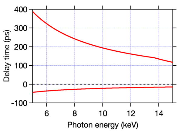
Fig. 2 Range of delay time as a function of photon energy. At positive delays the CC-branch pulse comes earlier.
ビームスプリッタ・マージャー(BS / BM)
SACLAのSDOでは、BS / BM素子として、結晶エッジ部を高精度に研磨した波面分割結晶(Fig. 3)を利用しています[1]。XFELの光軸上に結晶エッジ部を挿入し、BSに照射された部分のみ反射されdelayブランチへと、残りの部分はCCブランチへと分割されます(BMでも同様に、delayブランチのみBMによって反射されます)。この波面分割結晶により、同一のスペクトル分布を有する分割パルスの生成、結晶エッジ部の挿入位置制御による容易な強度比制御が達成されます。しかし、BM直後では空間的に分離されている分割ビームを試料面上で重複させる必要があるので、わずかではありますが、水平方向に試料への入射角度差が生じます。

Fig. 3 Conceptual picture of wavefront division with an edge-polished crystal (left) and an example beam profile measured just downstream of the SDO (right).
スペックルフリーチャネルカット結晶(CC1 / CC2)
CCブランチに利用されているチャネルカット結晶は、大阪大学山内研究室の独自技術である、Plasma Chemical Vaporization Machinig(PCVM)と呼ばれる加工技術を利用して開発されました[2]。チャネルカット結晶では、単一の素子においてX線が2回反射されるため、入射光軸と反射光軸との平行性を数ナノラジアンレベルで安定できる非常に有用な素子として知られています。しかし、構造上CMP(Chemical Mechanical Polishing)等の高精度無歪研磨技術の適用が難しく、表面の最終処理には機械的作用の強い研磨、もしくは溶液によるエッチングが利用されてきました。結果として、無歪かつ平滑な表面状態を達成することが難しく、反射ビームの波面が乱され、強度のモジュレーション(スペックル)が生じます。純化学的加工法であるPCVMにより最終表面処理を施すことで、無歪かつ平滑な表面状態を達成し、XFELの整った波面を維持することが出来ます(Fig. 3)。なお、PCVMはBL3 EH1に設置されているSi(111) DCCMにも適用されており、ポンプ・プローブ測定の高度化にも役立っています[3]。
SDOの性能
パルスエネルギー
SDOの各ブランチはSACLAにおいて汎用的に利用されている非破壊型の強度モニタを搭載しており、分割パルスそれぞれの相対パルスエネルギーをショット毎に計測することが出来ます。また、各実験ハッチに搭載されている、絶対値への変換係数が校正されたビームモニタを利用することで、ショット毎のパルスエネルギーの絶対値を導出することが出来ます。通常、より安定なCCブランチの強度モニタと校正されたビームモニタの2つを利用し、両分割パルスのパルスエネルギーを算出します。その場合、測定誤差は約5% rmsとなります(Fig. 4)。
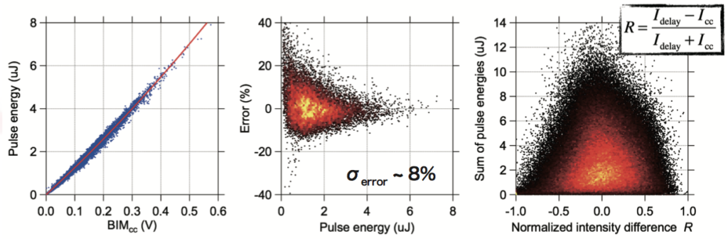
Fig. 4 Results of pulse energy diagnostics of SDO. (left) correlation between a calibrated beam monitor and a monitor at the CC branch measured by blocking the delay branch; (middle) Error distribution of the CC branch monitor; (right) sum of pulse energy vs normalized intensity difference between split pulses.
本光学系はSi(220)結晶により構成されているため、X線モノクロメータとしても機能します。相対バンド幅ΔE/E = 5.6 × 10⁻⁵の単色度を持ったXFELを利用できるというメリットがある一方で、多くのフォトンを失ってしまうというデメリットもあります。SASEモードでは、両分割パルス合わせて平均約0.5 μJとなります。近年開発されたSelf-Seedモード[4]では、単色性の高い高強度XFELを発生させることが出来るため、SDO利用時のパルスエネルギーは飛躍的に向上し、平均3 ~ 8 μJとなります。
遅延時間精度
BR1 / BR2結晶素子の移動量に伴う遅延時間変化量は精密に校正されており、誤差1%未満での遅延時間制御が可能です。また、時間差ゼロは自己相関法により実験毎に決定します[5]。非集光の分割ビームを部分的に重複させることで、遅延時間がコヒーレンス時間以下の場合、重複領域に干渉縞が生じます。干渉縞のビジビリティを評価することで、時間差ゼロを1~2 fsの精度で決定することが出来ます(Fig. 5)。

Fig. 5 Example result of autocorrelation measurement.
集光位置安定性
SDOの利用実験では一般的に集光ビームが利用されます。集光ビームの場合、数百ナノラジアンのビーム角度変動により集光位置が敏感に変化してしまいます。SACLAのSDOでは頑強な石定盤上に光学系が構築されており、各結晶の制御機構も高剛性なステージにより構成されているため、Fig. 6のように短期的にも長期的にも集光位置が安定します。
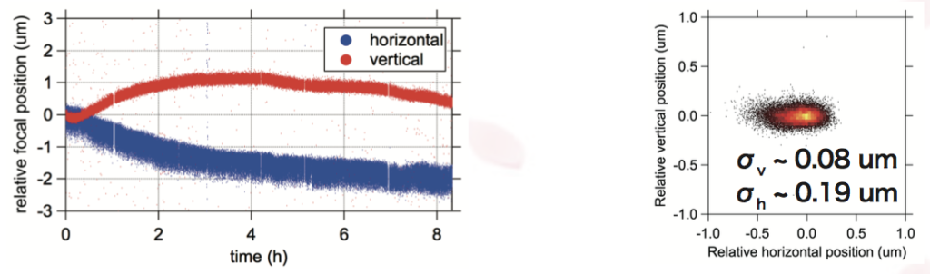
Fig. 6 (Left) long-term stability of relative focal pointing and (right) distribution of short-term pointing jitter. During this measurement, split beams are focused to 1 μm spot with a KB mirror system at EH4c.
遅延時間を変更した際も、ステージの姿勢変化により集光位置が変動してしまいます。ステージの姿勢変化には再現性があるので、遅延時間に対する集光位置変動にも再現性が確認されます(Fig. 7)。原理的には遅延時間変更時のポインティング変動も打ち消すことが出来ますが、連続的なステージ駆動による熱の発生により、集光位置のドリフトが大きくなります。従って、数μmオーダーでポインティングを安定させる必要がある場合、現在のところ遅延時間の連続的スキャンは困難です。
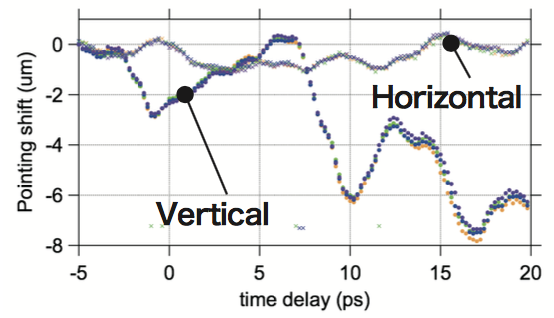
Fig. 7 Pointing stability during delay scans.
エネルギースキャン
本光学系では、遅延時間だけでなくX線エネルギーを変化させることも出来ます。これにより、X線ポンプ・X線プローブ分光測定が実現でき、X線励起に伴う電子状態変化のダイナミクスを測定出来ます。いずれのブランチに対してもエネルギーを変更することは出来ますが、光学系の安定性という観点から、一般的にはCCブランチのエネルギーをスキャンします。従って、遅延時間の正負が入れ替わります。また、一方のブランチのみエネルギー変更する場合、同時に遅延時間も変わってしまいますが、その補正も可能です。このような測定はバンド幅の広いSASEモードでのみ可能で、測定可能エネルギー範囲はSASEのバンド幅に依存し、およそ30 eV程度となります。

SDOの制御
複雑な光学系であるSDOですが、ユーザーフレンドリーなPythonモジュール(sdopy)を利用して制御することが出来ます。sdopyでは以下の操作を半自動的に行うことが可能です。
- 遅延時間の変更とそれに伴う各種機器の位置変更
- 各結晶素子の半自動再アライメント
- 強度モニタの絶対パルスエネルギーへの変換係数自動測定
- 分割パルス間の強度比分布の測定
- 各ブランチのエネルギー変更とそれに伴う各種機器の位置変更
source: /xdaq/work/share/SDO/sdopy.py
参考文献:
[1] T. Hirano et al., J. Synchrotron Rad. 25, 20 (2018).
[2] T. Hirano et al., Rev. Sci. Instrum. 87, 063118 (2016).
[3] T. Katayama et al., J. Synchrotron Rad. 26, 333 (2019).
[4] I. Inoue et al., Nat. Photon. 13</strong style="color: #0000ff;">, 319 (2019).
[5] T. Osaka et al., IUCrJ 4, 728 (2017).
SDO (Split-and-Delay Optics)
The BL3 OH has split-and-delay optics (SDO) permanently installed. By using SDO, a double pulse XFEL with a time delay can be generated by dividing one XFEL pulse, which enables branches with different optical path lengths to be propagated, then recombined on the same optical axis. By varying the optical path length for one branch, the time difference between split pulses can be controlled from approximately 0 fs to 100 ps, and X-ray excitation dynamics on the femtosecond to picosecond scale, as well as spontaneous fluctuations in the material, can be measured. This page introduces the elemental configuration and performance of SDO.
If you are planning an experiment using SDO, please be sure to contact the このメールアドレスはスパムボットから保護されています。閲覧するにはJavaScriptを有効にする必要があります。 for information on the available wavelength conditions before applying for an assignment.
※SDO was developed in collaboration with the group led by Professor Kazuto Yamauchi at Osaka University.
Configuration of the optical systems
Overall
Figure 1 displays the layout of SDO. The SDO at SACLA consists of a total of six Si (220) crystal optical devices. The XFEL pulse incident on the SDO is split into two replicated pulses by the first crystal beam splitter (BS). The first branch (blue) is reflected four times by two channel-cut crystals (CC1/ CC2) in the (+, –, –, +)arrangement (CC branch). The optical path length of the CC branch is fixed at a certain photon energy. In the other branch (red), in addition to the reflection from the BS, it returns to the same optical axis as the CC branch after a total of four reflections by two reflecting elements (BR1/ BR2) and the beam merger (BM). BR1 and BR2 are moveable in the direction perpendicular to the crystal surface, enabling control over the optical path length (delay branch). This optical system covers an energy range from 5 to 15 keV. The delay time range differs depending on the energy, please see figure 2 for information. The delay time can be set with a time step of 1 fs or less over the entire energy range. In addition, it is not effected by jitter, which are fluctuations in time synchronization which is a general problem for normal pump-probe measurements, and this enables delay time stability on the order of attoseconds.
This optical system is installed in a highly-hermetically sealed box, and the interior of the box can be replaced with He. When replacing with He, the box is feedback controlled to maintain the He concentration at 80%. In addition, no deterioration in stability has been observed with the introduction of He gas.
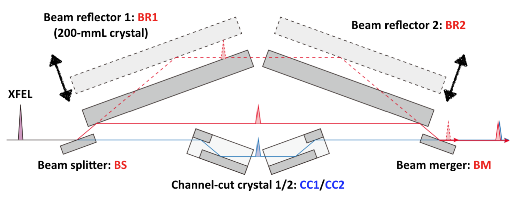
Fig. 1 Schematic optical layout of SDO system

Fig. 2 Range of delay time as a function of photon energy. At positive delays the CC-branch pulse comes earlier.
Beam splitter / merger (BS / BM)
The SDO at SACLA uses a wavefront splitting crystal (figure 3) with a crystal edge polished to high-precision as the BS/BM element [1]. The crystal edge is inserted on the optical axis of the XFEL, and only the part irradiated with the BS is reflected and divided into the delay branch, with the rest divided into the CC branch (Similarly in BM, only the delay branch is reflected with the BM). With this wavefront splitting crystal,
- split pulses with the same spectral distribution can be generated
- easy intensity matching control is possible by controlling the insertion position of the crystal edge
However, immediately after the BM, it is necessary to overlap the spatially separated split beams on the sample surface, to obtain a slight horizontal difference in the angle of incidence on the sample.
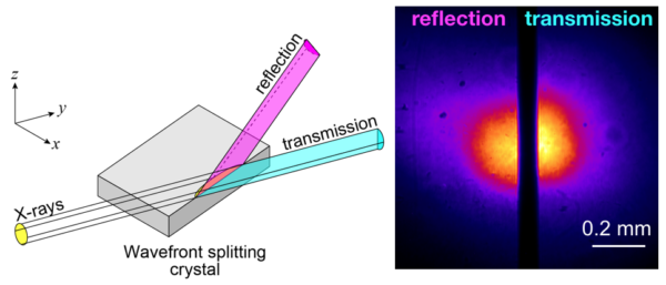
Fig. 3 Conceptual picture of wavefront division with an edge-polished crystal (left) and an example beam profile measured just downstream of the SDO (right).
Speckle free channel-cut crystals (CC1/ CC2)
The channel-cut crystal used in the CC branch was developed using a processing technology called Plasma Chemical Vaporization Machining (PCVM), which originated in the Yamauchi Laboratory of Osaka University [2]. With channel-cut crystals, X-rays are reflected twice within a single device, so they are very useful devices that can stabilize the parallelism between the incident optical axis and the reflected optical axis on the level of nanoradians. However, due to the structure, it is difficult to apply high-precision, distortion-free polishing techniques, such as CMP (Chemical Mechanical Polishing), so polishing with strong mechanical action or etching with a solution has been used for the final treatment of the surface. As a result, it is difficult to achieve a distortion-free, smooth surface, allowing for disruptions of the wave surface of the reflected beam, resulting in modulations in intensity (speckle). By applying PCVM to the final surface treatment, since it is a pure chemical processing method, it is possible to achieve distortion-free, smooth surface conditions, and maintain well-organized wave surfaces for XFEL (figure 3). PVCM is also applied to the Si(111) DCCM installed in BL3 EH1, and is used for improving pump-probe measurements [3].
SDO performance
Pulse energy
Each branch of SDO is equipped with a non-destructive intensity monitor that is commonly used at SACLA, and the relative pulse energy of each split pulse can be measured for each shot. In addition, by using the beam monitor equipped in the experimental hutch, which has the conversion coefficient calibrated to the absolute value, the absolute value of the pulse energy for each shot can be derived. Generally, the pulse energy of the split pulse is calculated using two stable CC branch intensity monitors and a calibrated beam monitor. In this case, the measurement error is approximately 5% rms (figure 4).

Fig. 4 Results of pulse energy diagnostics of SDO. (left) correlation between a calibrated beam monitor and a monitor at the CC branch measured by blocking the delay branch; (middle) Error distribution of the CC branch monitor; (right) sum of pulse energy vs normalized intensity difference between split pulses.
Since this optical system is comprised of Si(220) crystals, it also functions as an X-ray monochromator. While it has the advantage of being able to use XFEL with monochromaticity and a relative bandwidth ΔE/E = 5.6 × 10⁻⁵, it has the disadvantage of losing many photons. In the SASE mode, the total of both split pulses is approximately 0.5 μJ. With the recently developed self-seed mode [4], high-intensity XFEL with high monochromaticity can be generated, drastically improving the pulse energy when SDO is used, averaging between 3 - 8 μJ.
Accuracy of the delay time
The change in the delay time due to the amount of movement of the BR1/BR2 crystal elements is precisely calibrated, and the delay time can be controlled with an error of less than 1%. In addition, the zero time difference is determined for each experiment by the autocorrelation method [5]. Partial overlapping of unfocused split beams causes interference fringes in the overlapped region when the delay time is less than or equal to the coherence time. By evaluating the visibility of the interference fringes, it is possible to determine the zero time difference with an accuracy of 1 to 2 fs (figure 5).
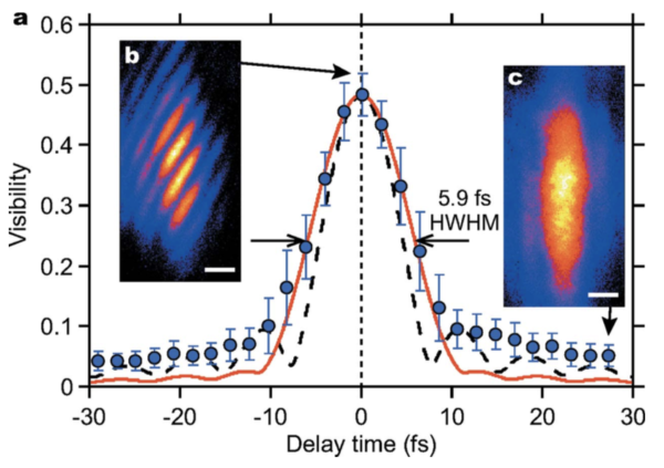
Fig. 5 Example result of autocorrelation measurement.
Stability of the focusing position
Focused beams are generally used in experiments with SDO. In the case of a focused beam, the focused position has sensitive changes due to fluctuations in the beam angle variations of several hundred nanoradians. With the SDO at SACLA, the optical system is build on a robust stone surface plate, and the control mechanism of each crystal is comprised of a highly rigid stage, shown in figure 6, enabling the focused position to remain stable in the short and long term.

Fig. 6 (Left) long-term stability of relative focal pointing and (right) distribution of short-term pointing jitter. During this measurement, split beams are focused to 1 μm spot with a KB mirror system at EH4c.
Even if the delay time is changed, the focused position will change due to the change in the position of the stage. Since the change in the position of the stage is reproducible, the reproducibility is confirmed in the change of the focused position with respect to the delay time (figure 7). In principle, pointing fluctuations occurring when the delay time changes can be cancelled out, but the drift at the focused position increases due to the heat generated by driving the continuous stage. Therefore, continuous scanning of the delay time is currently difficult when pointing needs to be stabilized on the order of a few μm.

Fig. 7 Pointing stability during delay scans.
Energy scan
With this optical system, not only the delay time, but also the X-ray energy can be changed. This enables X-ray pump/X-ray probe spectroscopy measurements and measurements of the dynamics of the electronic state changes associated with X-ray excitation. It is possible to change the energy for any branch, but from the perspective of optical system stability, the energy of the CC branch is typically scanned. Therefore, the positive and negative delay time are switched. Also, if you change the energy of only one branch, the delay time will change at the same time, but this can be compensated for. Such measurements are only possible in the wide bandwidth SASE mode, and the measurable energy range depends on the bandwidth of the SASE, but is approximately 30eV.
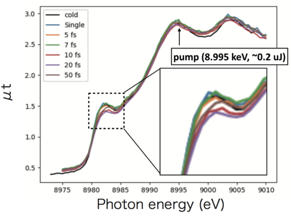
Fig. 8 Delay time dependence of absorption spectra of Cu.
SDO control
SDO is a complex optical system, but it can be controlled with a user-friendly Python module (sdopy). With sdopy, the following operations can be performed semi-automatically:
- Changes of delay time and changes of the position of various equipment
- Semi-automatic realignments of each crystal element
- Automatic measurements of the conversion coefficient to absolute pulse energy of the intensity monitor
- Measurements of the intensity ratio distribution between the split pulses
- Changes of the energy of each branch and position changes of various equipment
source: /xdaq/work/share/SDO/sdopy.py
References:
[1] T. Hirano et al., J. Synchrotron Rad. 25, 20 (2018).
[2] T. Hirano et al., Rev. Sci. Instrum. 87, 063118 (2016).
[3] T. Katayama et al., J. Synchrotron Rad. 26, 333 (2019).
[4] I. Inoue et al., Nat. Photon. 13</strong style="color: #0000ff;">, 319 (2019).
[5] T. Osaka et al., IUCrJ 4, 728 (2017).