大型表面X線回折装置(超高真空装置付)
◆装置概要
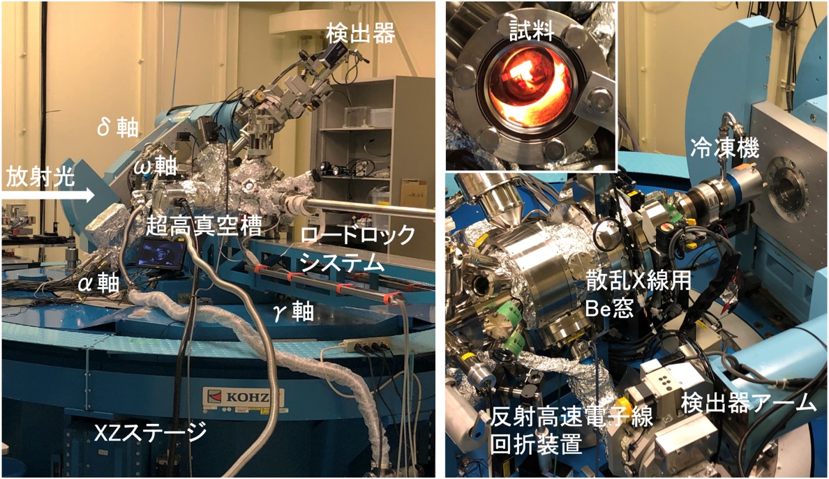
超高真空装置を備えた大型のS2+D2型回折装置です。超高真空環境でその場作製した表面層や埋もれた界面の原子レベル構造解析を行うことができます。

◆装置の特徴
各種超高真空槽を搭載した大型のS2+D2型回折計を用いて、超高真空環境でその場作製した表面層や埋もれた界面の原子レベル構造解析を行うことができます。制御ソフトウェアにはspec(https://www.certif.com)を利用しています。大型回折計は、試料、検出器ともに水平、垂直の両方向に回転の自由度をもち(S2+D2型の回折計)、大きさは、3.2×3.2×2.3(m)です。試料は水平ω軸(真空槽に据え付けられている)、および、大型回折計の垂直α軸によって回転します。X線検出器用の回転軸として、水平δ軸、および、垂直γ軸があり、垂直軸は、試料用(α軸)と検出器用(γ軸)とが独立に駆動します。表に各回転軸の角度分解能の一覧を示す。
検出器には、イオンチャンバ、シリコンPINフォトダイオード検出器、シンチレーション検出器(Oxford x2000)、イメージングプレート検出器、一光子計測二次元検出器(Pilatus-100K, HyPix-400, HyPix-9000)が利用可能です。
エネルギー領域6 keVから30 keV程度(条件により50 keVまで)のX線が利用でき、最大ビーム強度は6×10¹³ 光子数/秒(@12.4 keV)です。利用時のビームサイズは100 μm程度が標準的です。
表 回折計の各軸の分解能(arc sec/motor step)
| Axis | Step (arc sec) |
| ω1 | 0.72 |
| ω2 | 0.72 |
| ω3 | 0.09 |
| α | 0.36 |
| δ | 0.36 |
| γ | 0.36 |
| μ | 3.6 |
◆装置アクセサリー
超高真空槽は、清浄表面作製用の加熱装置(通電加熱・傍熱加熱・電子衝撃加熱)とイオンスパッタリング装置、蒸着源、ガス導入系、真空計、表面構造評価用の低速電子回折装置、反射高速電子回折装置、膜厚モニタ、四重極質量分析計を備えています。目的に応じて3台の超高真空槽が用意されており、そのうちの1台は、試料基板温度を20 Kから1200 Kまで制御可能です。試料アライメントのためのモーター駆動調整ステージ5軸(平行移動3軸、あおり2軸)や入射ビーム成形スリット、ビーム位置安定化システム(MOSTAB)も備えています。
◆実験・試料準備
表面・界面のその場作製・その場観察を希望される方は、効果的な課題実施のために、ビームタイムより前に本装置を用いたオフラインでの調整実験(試料作製条件出し、装置ベーキング、試料アライメントを含む)を実施されることを推奨します。
試料基板サイズが5〜10 mm程度であれば、標準の試料マニピュレータに取り付けできます。それ以外のサイズでの測定を希望される場合はBL担当者にお問い合わせください。また、ビームタイム開始時には、毎回、装置の角度精度を保証するために光源・光学系・回折装置のアライメントを実施しています。
◆実験手順・注意事項
制御ソフトウェアとして採用しているspec(https://www.certif.com)は、単純なコマンド入力で目的とする逆格子空間へ容易にアクセスできる他、強力なマクロ機能により煩雑な測定手順を自動化できます。一方で、標準のユーザインターフェイスがCUI(Character User Interface)である点にご注意ください。
本装置を初めて利用される方、あるいは、これまでとは異なる測定法・測定条件を検討しておられる方は、実験課題を効果的に実施するために課題申請前にかならずBL担当者と打ち合わせをおこなうことを推奨します。
◆問い合わせ先
田尻寛男 (このメールアドレスはスパムボットから保護されています。閲覧するにはJavaScriptを有効にする必要があります。)
◆代表的な論文リスト
[1] "Beamline for surface and interface structures at SPring-8",
O. Sakata, Y. Furukawa, S. Goto, T. Mochizuki, T. Uruga, K. Takeshita, H. Ohashi, T. Ohata, T. Matsushita, S. Takahashi, H. Tajiri, T. Ishikawa, M. Nakamura, M. Ito, K. Sumitani, T. Takahashi, T. Shimura, A. Saito, and M. Takahasi,
Surf. Rev. Lett., vol.10, pp.543-547 (2003).
DOI: 10.1142/S0218625X03004809
[2] “Dynamical fluctuations in In nanowires on Si(111) ”,
S. Hatta, Y. Ohtsubo, T. Aruga, S. Miyamoto, H. Okuyama, H. Tajiri, and O. Sakata,
Phys. Rev. B, vol.84, pp.245321-(1-8) (2011).
DOI: 10.1103/physrevb.84.245321
[3] “Characterization of the ScAlMgO4 cleaving layer by X-ray crystal truncation rod scattering”,
T. Hanada, H. Tajiri, O. Sakata, T. Fukuda, T. Matsuoka,
J. Appl. Phys., vol. 123, pp.205305-(1-8) (2018).
DOI: 10.1063/1.5031024
[4] “Spontaneous Distortion via the Appearance of Ferromagnetism in Pd Ultrathin Films: Observation of an Inverse Mechanism for the Stoner Criterion”,
S. Sakuragi, H. Tajiri, H. Kageshima, T. Sato,
Phys. Rev. B, vol.97, pp214421-(1-5) (2018).
DOI: 10.1103/PhysRevB.97.214421
[5] “Progress in surface X-ray crystallography and the phase problem”
Hiroo Tajiri
Jpn. J. Appl. Phys., vol.59, pp.020503-(1-12) (2020).
DOI: 10.7567/1347-4065/ab631e
Large Surface X-ray Diffraction Equipment (Including Ultra High-Vacuum Equipment)
◆Equipment overview
It is a large S2+D2 diffractometer equipped with ultra high-vacuum devices. This allows for atomic-level structure analysis of surface layers and covered interfaces in ultra high-vacuum environments.

◆Features of the Equipment
Using a large S2+D2 diffractometer equipped with various ultra high-vacuum chambers, it is possible to perform atomic-level structure analysis of surface layers and covered interfaces in a ultra high-vacuum environment. The control software used is Spec(https://www.certif.com).The large diffractometer has rotational freedom in both horizontal and vertical difractions for both samples and detectors (S2+D2 diffractometer), and is 3.2×3.2×2.3(m) large. The sample is rotated on the horizontal ω-axis (mounted in a vacuum chamber), and, the large diffractometers vertical α-axis. The axis of rotation for X-ray detectors are the horizontal δ-axis and vertical γ-axis, which are driven independently of the sample (α-axis) and detector (γ-axis). The table shows a list of angular resolution for each axis of rotation.
The available detector instruments are: an ion chamber, a silicon PIN photodiode detector, a scintillation detector (Oxford x2000), an imagine plate detector, and single photon measurement 2-dimensional detectors (Pilatus-100K, HyPix-400, HyPix-9000).
X-rays in the energy region of 6 keV to 30 keV (with a maximum of 50 keV depending on the conditions) are available, with a maximum beam intensity of 6×10¹³ photons/second (@12.4 keV). The standard beam size used is about 100μm.
Table Resolution of Each Axis of the Diffractometer (arc sec/motor step)
| Axis | Step (arc sec) |
| ω1 | 0.72 |
| ω2 | 0.72 |
| ω3 | 0.09 |
| α | 0.36 |
| δ | 0.36 |
| γ | 0.36 |
| μ | 3.6 |
◆Equipment accessories
The ultra high-vacuum chamber is equipped with the following instruments: a heating device for cleaning surfaces (electric heating, indirect heating, and electron impact heating), ion sputtering equipment, vacuum deposition source, gas introduction system, a vacuum gauge, low-speed electron diffraction device for surface structure evaluation, reflective high-speed electron diffraction device, film thickness monitor, and a quadrupole mass spectrometer. 3 ultra high-vacuum chambers are available depending on the purpose, one of which can control the sample substrate temperature from 20K to 1200K. The device features a motor driven adjustment stage with 5 axes (3 translation axes, 2 impact axes) for sample alignment, as well as an incident beam forming slit, and a beam position stabilization system (MOSTAB).
◆Experiment / sample preparation
If you wish to observe surfaces and interfaces or field creation and field observation, to implement effective subjects, it is recommended to conduct offline adjust experiments (including preparing the conditions, equipment baking, and sample alignment) before beam time.
If the sample substrate size is between 5-10 mm, it can be attached to a standard sample manipulator. If you would like to measure larger sizes, please contact the BL representative. In addition, at the start of the beam time, the alignment of light sources, optical systems, and diffraction devices are performed every time to guarantee the angle accuracy of the device.
◆Experimental procedure / precautions
The control software used is Spec (https://www.certif.com), which allows for simple command input that provides easy access to the reciprocal lattice space, where powerful macro functions automate troublesome measurement procedures. On the other hand, please note that the standard user interface is the CUI (Character User Interface).
If you are using this device for the first time, or if you are considering different measurement methods or conditions, in order to effectively implement the experimental objectives, it is recommended that you meet with the person in charge of the BL before applying for the assignment.
◆Contact
田尻寛男 (このメールアドレスはスパムボットから保護されています。閲覧するにはJavaScriptを有効にする必要があります。)
◆List of representative treatises
[1] "Beamline for surface and interface structures at SPring-8",
O. Sakata, Y. Furukawa, S. Goto, T. Mochizuki, T. Uruga, K. Takeshita, H. Ohashi, T. Ohata, T. Matsushita, S. Takahashi, H. Tajiri, T. Ishikawa, M. Nakamura, M. Ito, K. Sumitani, T. Takahashi, T. Shimura, A. Saito, and M. Takahasi,
Surf. Rev. Lett., vol.10, pp.543-547 (2003).
DOI: 10.1142/S0218625X03004809
[2] “Dynamical fluctuations in In nanowires on Si(111) ”,
S. Hatta, Y. Ohtsubo, T. Aruga, S. Miyamoto, H. Okuyama, H. Tajiri, and O. Sakata,
Phys. Rev. B, vol.84, pp.245321-(1-8) (2011).
DOI: 10.1103/physrevb.84.245321
[3] “Characterization of the ScAlMgO4 cleaving layer by X-ray crystal truncation rod scattering”,
T. Hanada, H. Tajiri, O. Sakata, T. Fukuda, T. Matsuoka,
J. Appl. Phys., vol. 123, pp.205305-(1-8) (2018).
DOI: 10.1063/1.5031024
[4] “Spontaneous Distortion via the Appearance of Ferromagnetism in Pd Ultrathin Films: Observation of an Inverse Mechanism for the Stoner Criterion”,
S. Sakuragi, H. Tajiri, H. Kageshima, T. Sato,
Phys. Rev. B, vol.97, pp214421-(1-5) (2018).
DOI: 10.1103/PhysRevB.97.214421
[5] “Progress in surface X-ray crystallography and the phase problem”
Hiroo Tajiri
Jpn. J. Appl. Phys., vol.59, pp.020503-(1-12) (2020).
DOI: 10.7567/1347-4065/ab631e
